
Concepts
Theorical concepts
In this chapter, you will go through a detailed explanation about key engineering concepts and components such as motors, encoders, ultrasonic sensors, I2C communication, PWM signals, and LiPo batteries.
3.1 DC Motors
DESCRIPTION
A DC (Direct Current) motor is a type of motor that will cause the motor shaft to rotate around its longitudinal axis when applying an electric current between its terminal pins. Thus, the DC motor is a type of actuator that transforms electrical current into rotational motion.
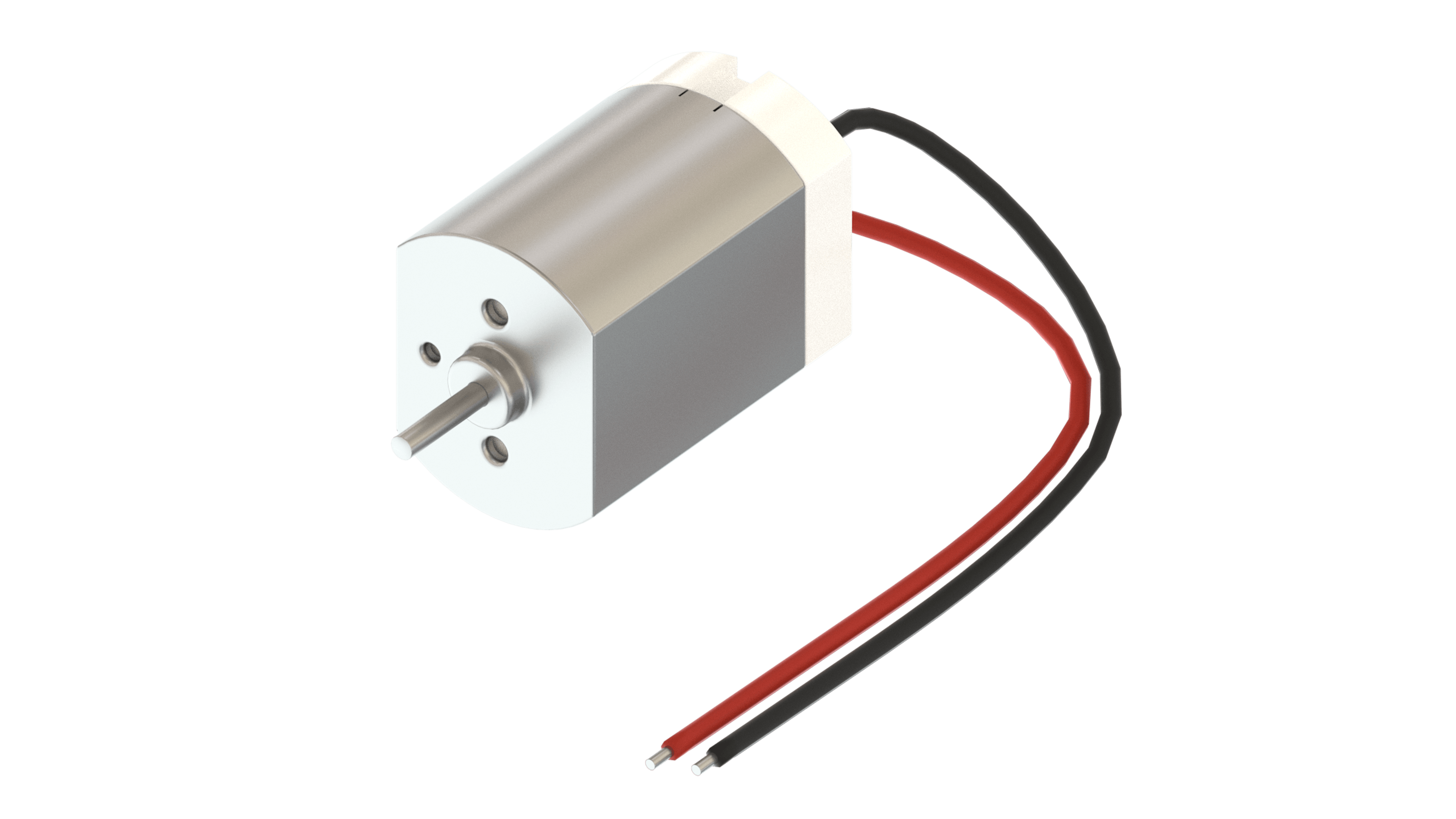
This is a DC motor. At the top of the left image, you can see the shaft; the visible end of the spinning part of the motor. In the image on the right, you can see where to apply the voltage on the two terminals.
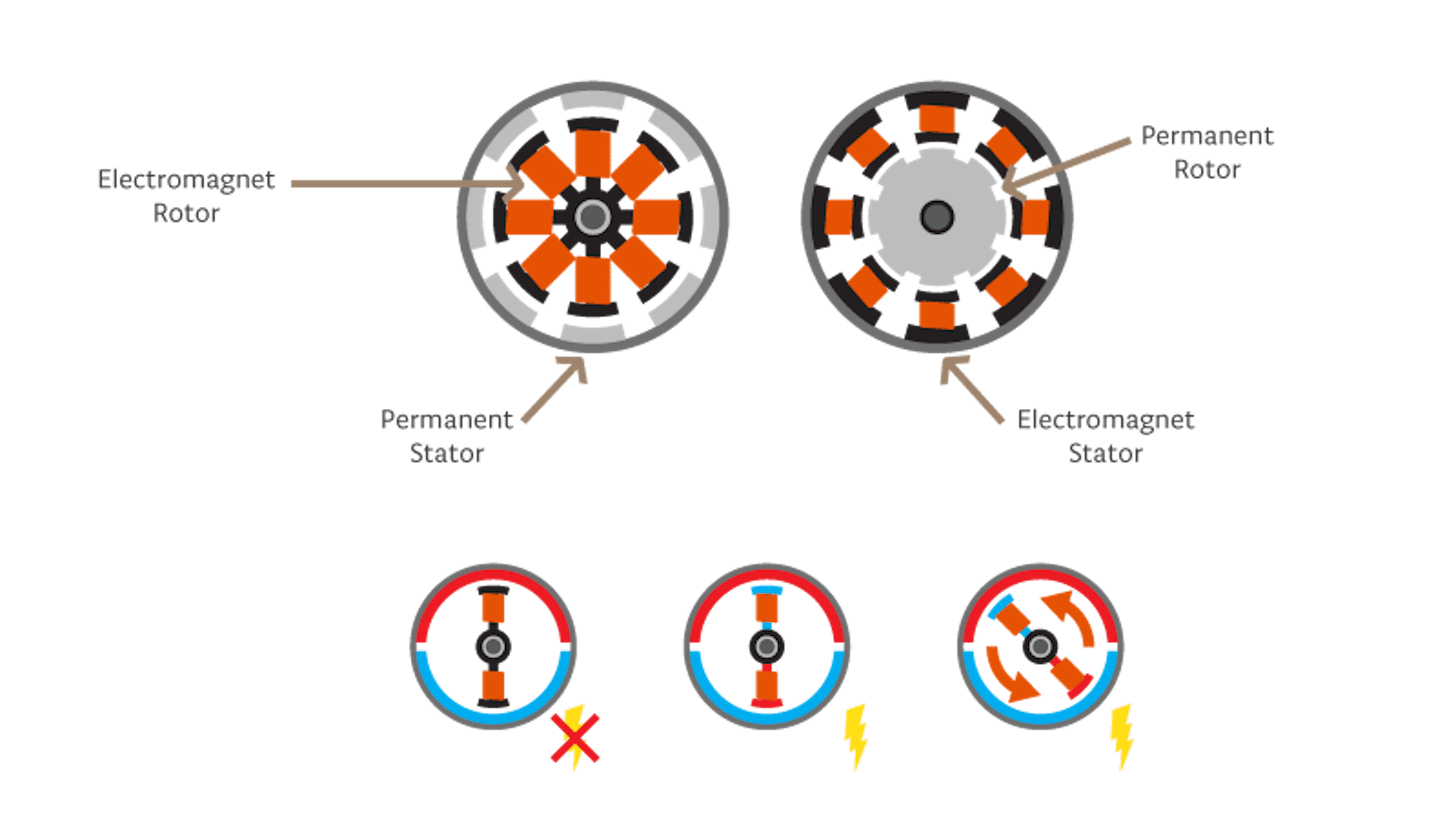
There are two parts inside a motor: the rotor (the shaft is part of this) and the stator. Looking at the cross-section of a motor, you can see that the rotor is the moving part and the stator is the static part. The stator and the rotor use both permanent magnets and electromagnets. Depending on the type of motor, the stator can be a permanent magnet while the rotor is an electromagnet, or vice-versa. Turning on the electromagnet creates attraction and repulsion forces that make the motor spin.
The DC motor spins when we apply DC voltage through its two terminal pins. We can vary the speed of the motor by changing the voltage level. Also, motors can run freely in both directions just by reversing the direction of the current.
DC motors alone are not very good for precise movement, but they can provide very high rotational speeds.
HOW TO DRIVE MOTORS
Most electric motors need a higher voltage than can be provided by a microcontroller. To control a DC motor from a microcontroller, you’ll need to use a driver. This can be a transistor, a relay or an H-Bridge. The Arduino Motor Carrier uses H-Bridges to drive the DC motors.
The H-Bridge is an electronic circuit that contains four transistors arranged so that the current can be driven to control the direction of the spin and the angular speed. There is a more in-depth explanation of the H-Bridge in section 3.1.4. It is common practice to use PWM (Pulse Width Modulation) signals to control the speed of a motor instead of providing analog voltages.
With the Arduino IDE, if you want to just turn a DC motor on and off, you can use a digitalWrite command with HIGH for ON and LOW for OFF. If you instead want to modify the speed of the motor, you can use the analogWrite command and one of the PWM pins.
MAIN CHARACTERISTICS OF MOTORS
When searching for a motor, there are some parameters that you should look for in the motor’s datasheet:
- Speed: This is commonly presented in RPM (Revolutions per minute), and it gives you a reference of how fast the motor can spin. Keep in mind that some parameters are measured under specific conditions. If you add a load to the motor, the motor will go slower, so you might have to customize your motor speed to your particular project. In the datasheets, this parameter is commonly measured as no load. This indicates the maximum speed the motor can reach. In Chapter 2, we showed you how to characterize a motor. This is something that will be repeated in different ways for each one of the projects, as all of them use motors in different configurations.
- Stall Torque: This is commonly presented in kg-cm and sometimes in Newton-meters, and it gives you a frame of reference for the maximum strength of the motor (i.e., when the motor can no longer rotate because of overload).
- Stall current: The amount of electric current in Amperes that is consumed by the motor under a maximum load.
- Operating voltage: The range of voltages that the motor is designed to work within.
GEARBOXES
For some projects, you might need more torque or the ability to slow down your motor’s speed. To achieve this, you can add a gearbox (or buy a motor with one included). Gearboxes come in different reduction rates (e.g., 1:100, 1:1000, etc.). The rule of thumb is the higher the reduction rate the more torque you get, and the slower the maximum resulting speed.
DC MOTORS IN THE KIT
In this kit we will use two micro DC motors with a gearbox (100:1), an encoder and a bigger DC motor. The small geared motors will be used to move the wheels of the rover, to lift the drawing robot, and to drive the motorcycle forwards and backwards. The bigger DC motor (without gearbox) will be used to move the inertia wheel in the motorcycle project.
The specs of the micro motors with the encoder are:
- Speed (No load): 320 RPM
- Stall Torque: 2.2 Kg-cm
The specs of the bigger motor are:
- Speed (No load): 7500 RPM
- Stall torque: 150g-cm
HARDWARE TEST
Now that we have more detailed information about the motors we are going to use in the projects, let's learn how to work with them using Arduino.
Following, we are going to learn how to modify the speed and direction of the motor. Then we will see how to read from an encoder and send that information to the serial port.
To test the motors and encoders, we will need:
- Arduino MKR1000
- MKRMotorCarrier
- DC Geared Motors
- Encoders
- LiPo battery
The MKRMotorCarrier has four holders to connect motors (M1, M2, M3 and M4) and two to connect encoders (HA1/HB1 and HA2/HB2).
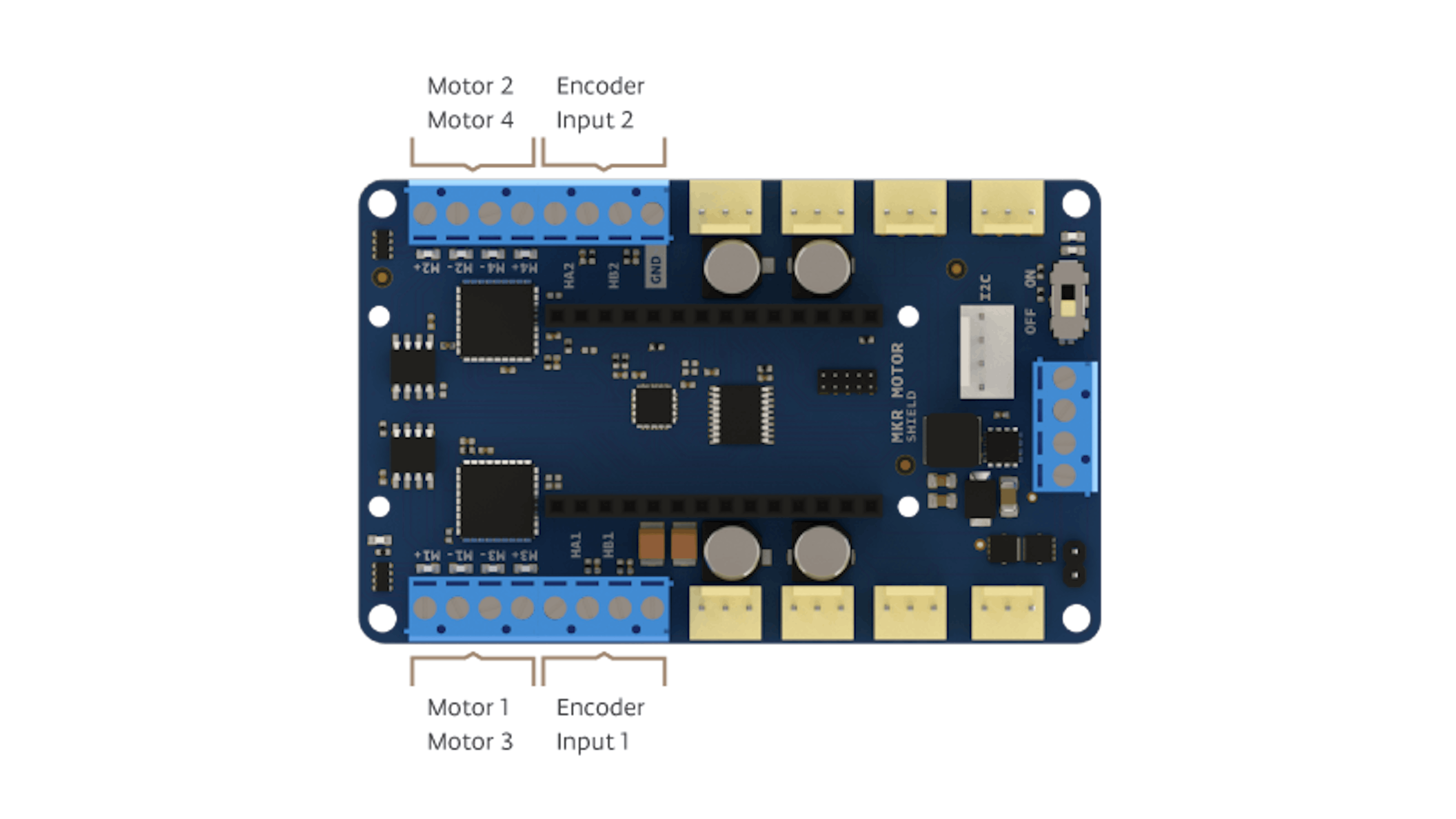
Let's start connecting the motor to the holder M1 and the encoder to the HA1/HB1. We show you how to do it in the code example.
First of all, we are going to move the motor. To do that, upload this code to your MKR1000:
Once we know how to move a motor, the next step is to read from the encoders. To do that, upload the next code to your MKR1000.
EXPECTED RESULTS
After running the first sketch you should appreciate that the motors turns making a sweep since stop position until highest speed in both directions. You can connect the motor on any of the motor connectors, the behavior of it should be the same.
In the second sketch you should choose the motor that you are going to use and the encoder, once you have done it, in the serial port you could see the encoder counts and the motor speed in counts per second, also, the duty cycle of the motor. In function of the motor connections and the motor turning direction, the speed and the encoder counts could be positive and negative.
TROUBLESHOOTING
If you don’t have the expected behavior after you have run the first sketch:
- Check that the MKRMotorCarrier is ON
- Check that the motors are connected in the motor connectors
- Check the back part of the motors, be sure that the black disk is not touching the PCB components.
- Try to move the motor axis by hand
If you don’t have the expected behavior after you have run the second sketch:
- Check that the MKRMotorCarrier is ON
- Check the encoder connections
- Be sure that the battery is charged
- Update the MKRMotorCarrier firmware uploading the example: File -> Examples -> MKRMotorCarrier -> Flasher
TO LEARN MORE
You can see more detailed specs of the motors here:
3.2 Encoders
DESCRIPTION
Magnetic encoders are sensors that can report information about the rotation speed and the spinning direction of the motor when mounted on a motor. A common way to use magnetic encoders is to attach them to the motors driving the wheels of a robot. In doing so, the sensor will be able to detect the speed of the robot, the direction (angular rotation direction), and the distance traveled (by knowing the robot’s wheel radius).
HALL SENSOR-BASED ENCODERS
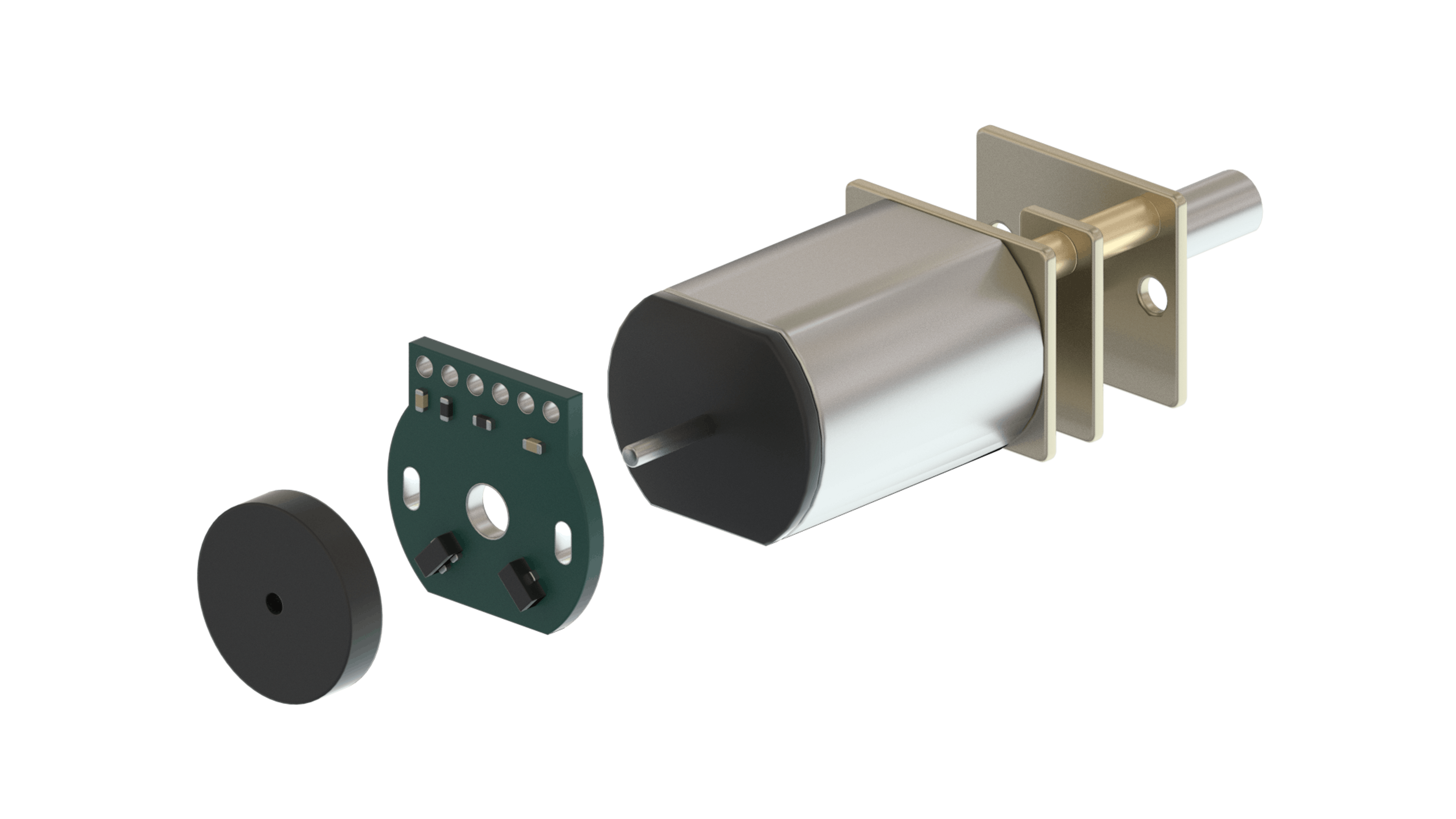
The magnetic encoders are composed of a module with two Hall-effect sensors and magnetic discs.
A Hall effect sensor is capable of detecting the Hall effect (not surprisingly). This consists of the production of a voltage difference across an electrical conductor when a magnetic field is applied. As the motor turns, the disc rotates past the sensors. Each time a magnetic pole passes a sensor, the encoder outputs a digital pulse, also called a “tick”. By counting those ticks, the speed of the motor can be determined.
ENCODER OUTPUT SIGNALS
The encoder has two outputs, one for each Hall effect sensor. The sensors are positioned so that there is a phase of 90 degrees between them. This means that the square wave outputs of the two Hall effect sensors on one encoder are 90 degrees out of phase. This is called a quadrature output.

The picture above shows the typical output of an encoder. Having the output pulsing 90 degrees out of phase allows the direction of the motor’s rotation to be determined. If output A is ahead of output B, the motor is turning forward. If output A is behind output B, the motor is turning backward.
As explained earlier, by measuring the frequency of the pulse signal in A or B (in this case it’s not important from which one), we will obtain the speed at which the motor is turning. This information can then be used to obtain linear speed (e.g., the speed of a vehicle).
ENCODERS IN THE KIT
In this kit we are going to use the magnetic encoders to calculate the position of the drawing robot on the whiteboard and the position of the rover in the arena. The encoder will be attached to a geared DC motor and the encoder outputs will be connected to the motor carrier.
TO LEARN MORE
More information about encoders can be found here
3.3 Servo motors
DESCRIPTION
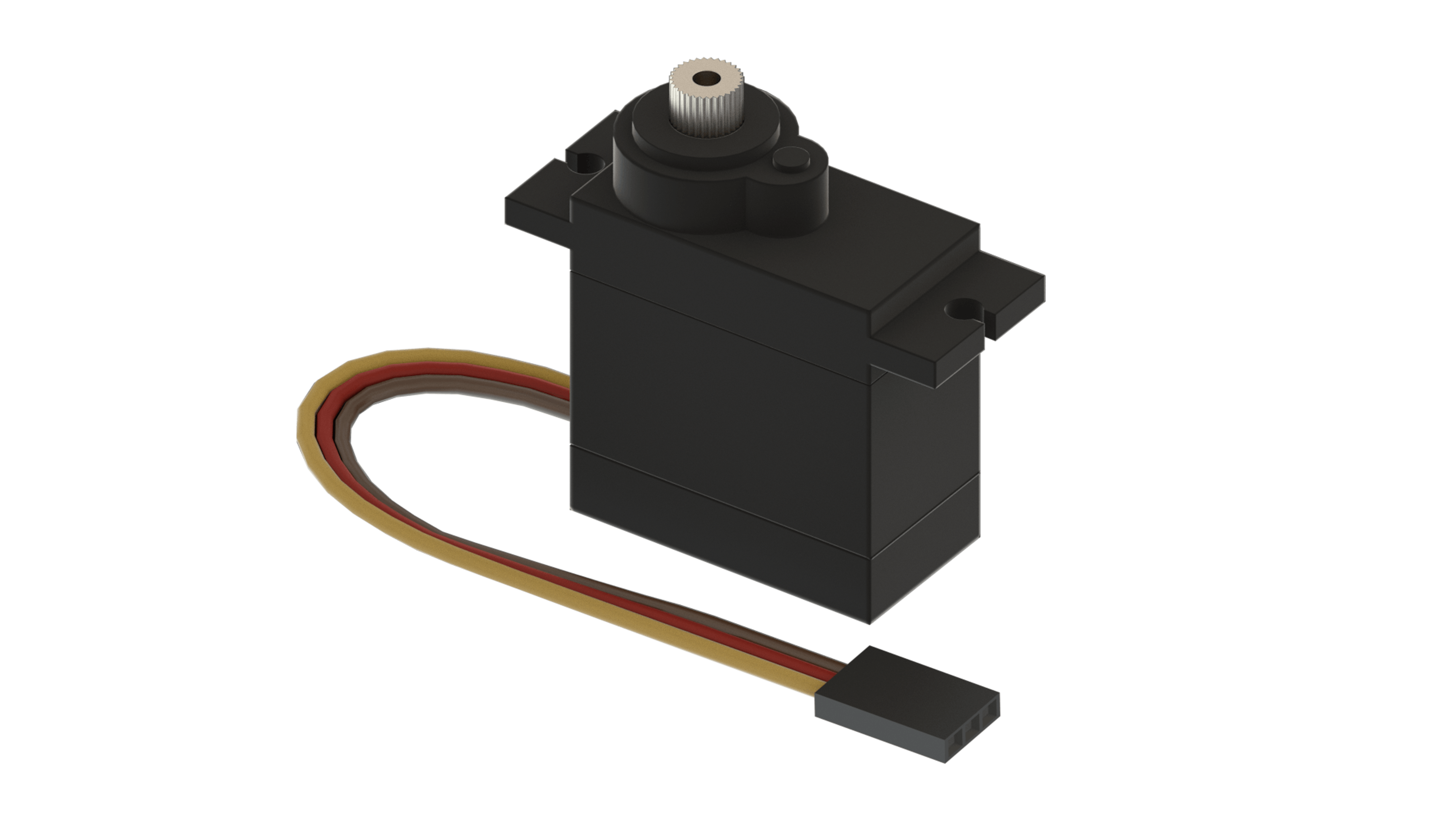
Servo motors are actuators that allow for precise control of position (angle) or angular velocity from a microcontroller. Servo motors have an embedded control circuit inside the housing. This circuit can be analog or digital, and this is determined by the kind of functions the motor is designed to perform. From a functional perspective, there are two types of servo motors: the standard servo and continuous rotation servo.
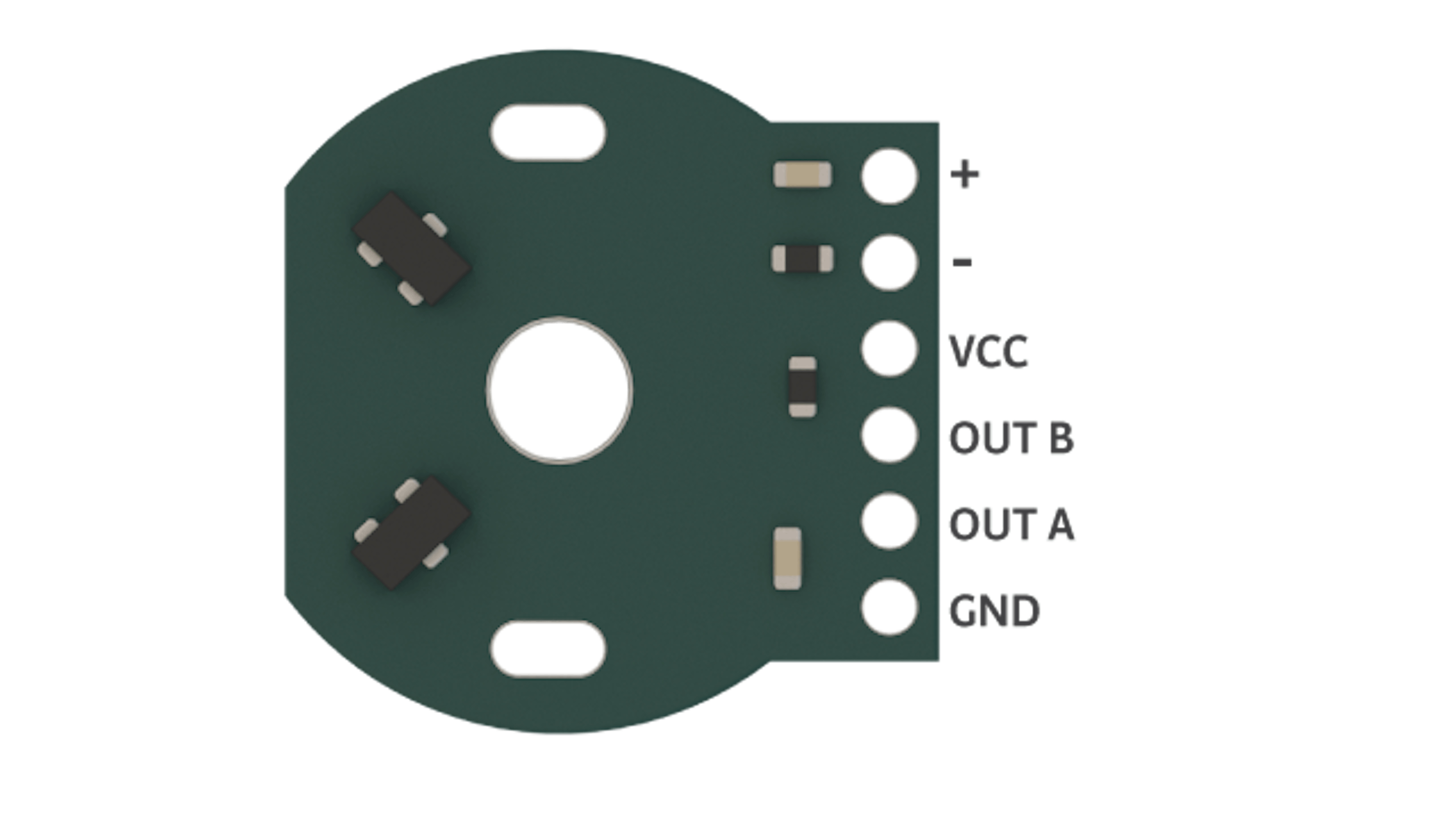
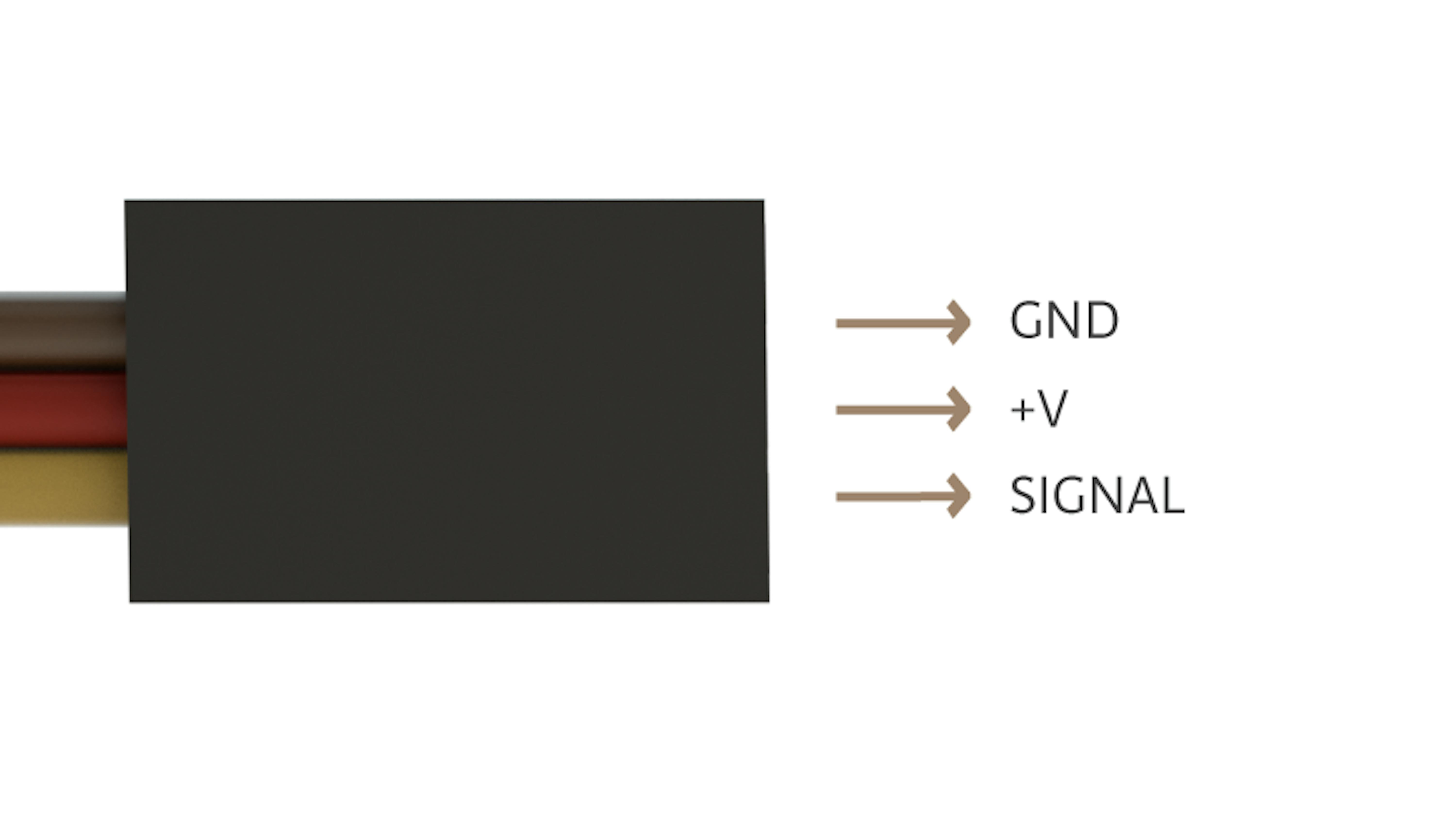
Servo motors have three terminals, one for ground (GND), one for power (5V) and one for the control signal. It is important to double-check the pinout of your servo motor as it might vary from manufacturer to manufacturer.
STANDARD SERVO
A standard servo has positional control and it can accurately turn to a specific degree. Its range is usually from 0° to 180°, although there are some servos with more or less range.
A standard servo cannot continuously rotate like a DC motor, so it can’t be used to drive a wheel. However, it can be used to move things back and forth at specific angles with high accuracy. For instance, if it is used on the lid of a box, it can open the lid by turning to the 90° position. It can then close the lid by returning to the 0° position.
A standard servo actually uses a DC motor, but it also has a gearbox, a position sensor, and a control circuit. These components work together to allow the servo to precisely move from one position to the other.
CONTINIOUS ROTATION SERVO
The continuous rotation servo is similar to a standard servo from a construction point of view, as it uses a DC motor, a gearbox, and a motor control circuit.
When triggered with the right signal, it turns in a similar fashion to that of a basic DC motor, but not as fast. Both servos can turn and change direction and speed, but continuous servos offer more precise control and do not need an external driver or an H-bridge to work. They can be directly connected to the microcontroller board.
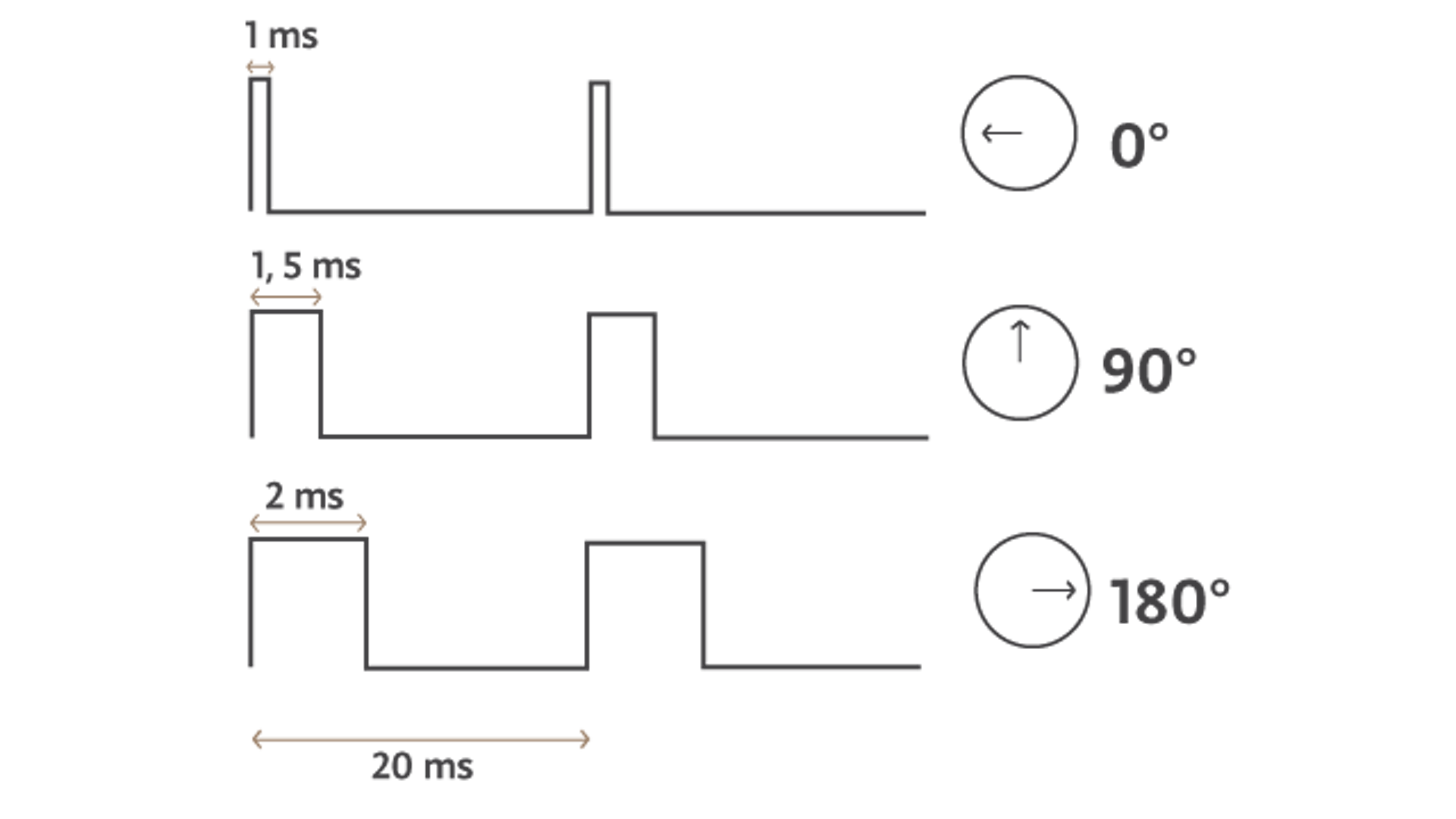
PULSE POSITION MODULATION
To control servo motors, we use Pulse Position Modulation (PPM) signals. They are a specific type of pulsated signal that operates at a fixed frequency. The PPM value is translated to a turning angle for standard servos, and direction and speed for continuous servos.
PPM signals can be generated from the PWM pin on a microcontroller board. In the Arduino IDE, there is a servo library available for your use. This library allows you to send pulses into the servo at the right intervals in the background, thus allowing that Arduino to continue running the remaining code.
SERVO MOTORS IN THE KIT
The Arduino Engineering Kit comes with one servo motor that will be used in all three of the following projects.
- Motorcycle: the servo motor will be used in the front to steer the motorcycle.
- Rover: the servo motor will be used for the lifting mechanism in the front of the rover.
- Drawing robot: the servo motor will be used in the mechanism to change the pen color.
HARDWARE TEST
Now it’s time to test the servos. The MKRMotorCarrier give us the possibility to connect four servos and control them at the same time. We are going to learn how to control the servo motor in our kit. To do it, we have to find the servo connectors on the board.
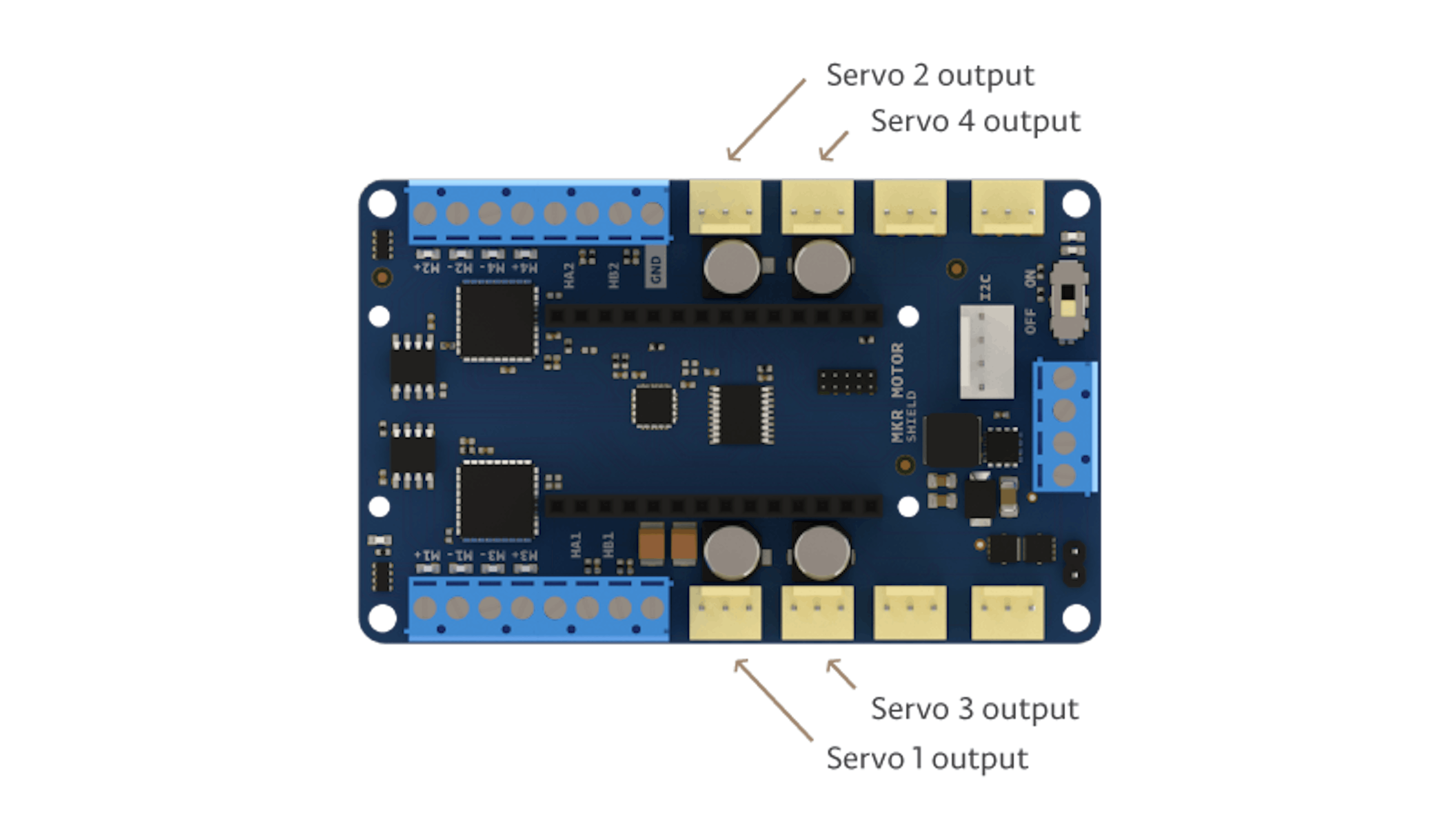
Make sure that you are connecting the servo in the right position, we show you how to do it in the code example.
These materials are needed to control the servo:
- Arduino MKR1000
- MKRMotorCarrier
- Servo
- LiPo battery
Upload in your MKR1000 this sketch to see how to control the servo movements:
EXPECTED RESULTS
Once the sketch is running in your MKR1000, you should see the on the Serial Port window the position of the servo and your servo should be sweeping from 0 position to 180.
TROUBLESHOOTING
If it’s not the behavior that you are getting, check:
- That the servo connector is in the right position and that it’s not inverted
- The MKRMotorCarrier is ON
- Disconnect the servo and try to move the axis by hand
- Update the MKRMotorCarrier firmware uploading the example: File -> Examples -> MKRMotorCarrier -> Flasher
TO LEARN MORE
More information about servos can be found below.
- Datasheet of the servo motor
- The Arduino servo library can be found here and here
3.4 H-Bridge
DESCRIPTION
An H-Bridge is an electronic circuit that allows us to change the voltage direction applied to a load. It is commonly used to change the direction and the speed of a DC motor. In addition, H-bridges are also used as motor drivers, since microcontrollers usually don’t have enough current to power an electric motor.
An H-Bridge contains four switches that are controlled in pairs. The current flows in a different direction depending on which switches are activated. This allows the direction of the motor itself to be controlled.
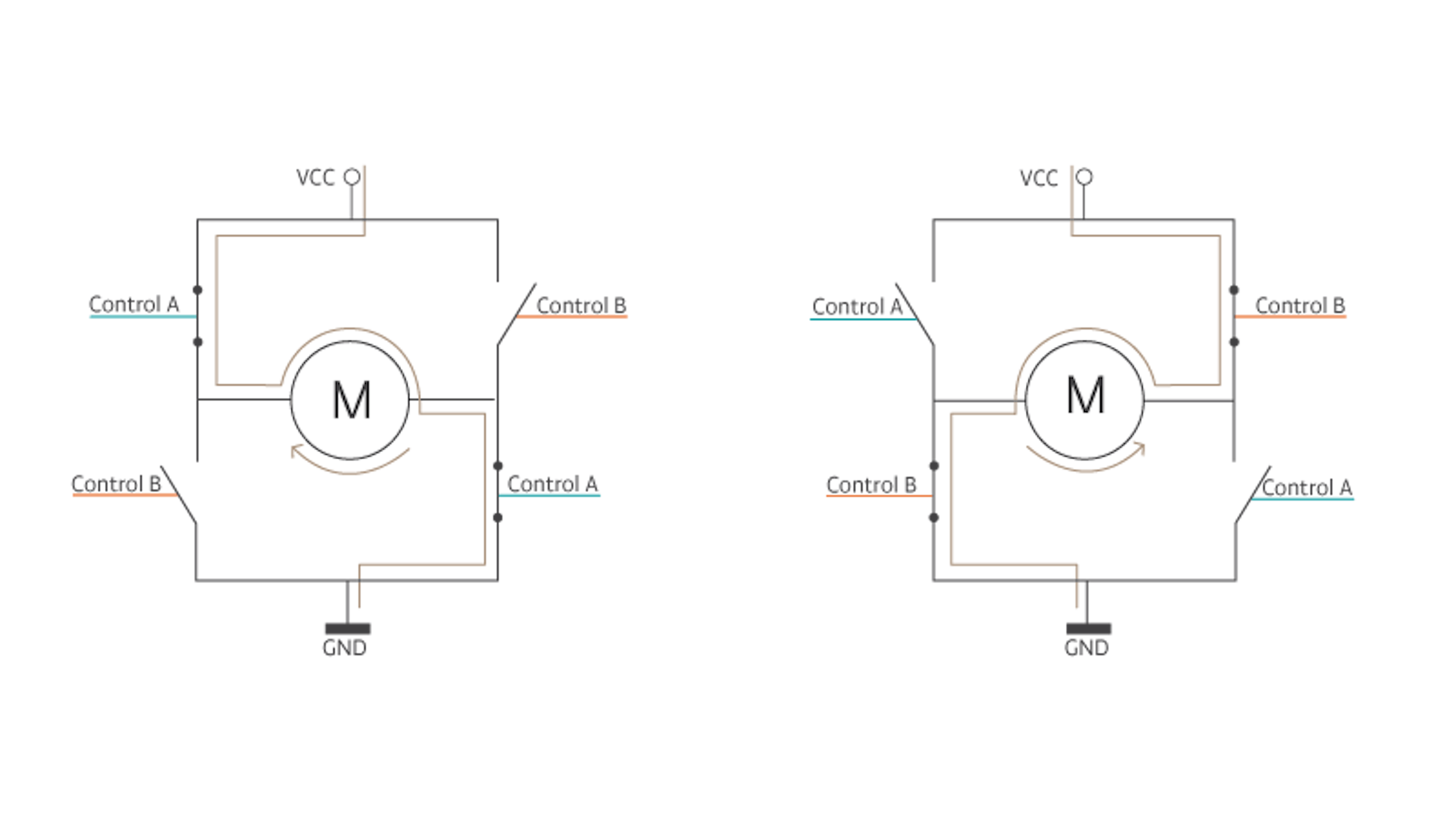
The image above shows a simplified version of the internal structure of an H-bridge and how the switches can be controlled to change the motor’s direction.
If we consider a logical HIGH level when the switch is closed and LOW level when the switch is opened, we have the following behavior.
TYPES OF SWITCHES
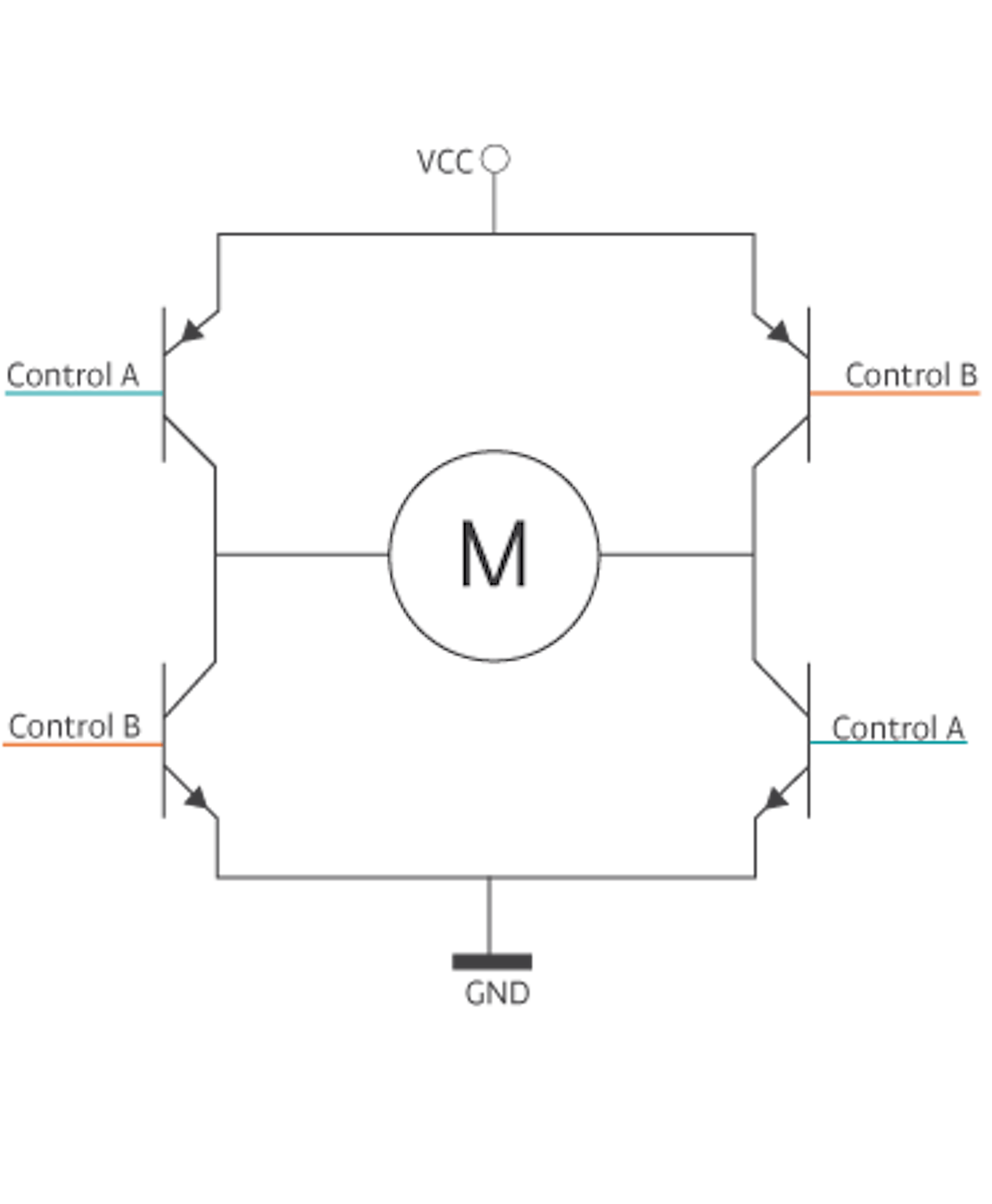
As explained above, one H-Bridge has four switches that make it possible to control the motor. These switches are usually transistors. Depending on the model of the transistors, the bridge will have different characteristics.
- BJT (Bipolar Junction Transistor) Transistors as switches. These bridges can control low-power motors. The BJT’s are easy-to-use transistors, but they have low efficiency and can’t drive a high current through the motors.
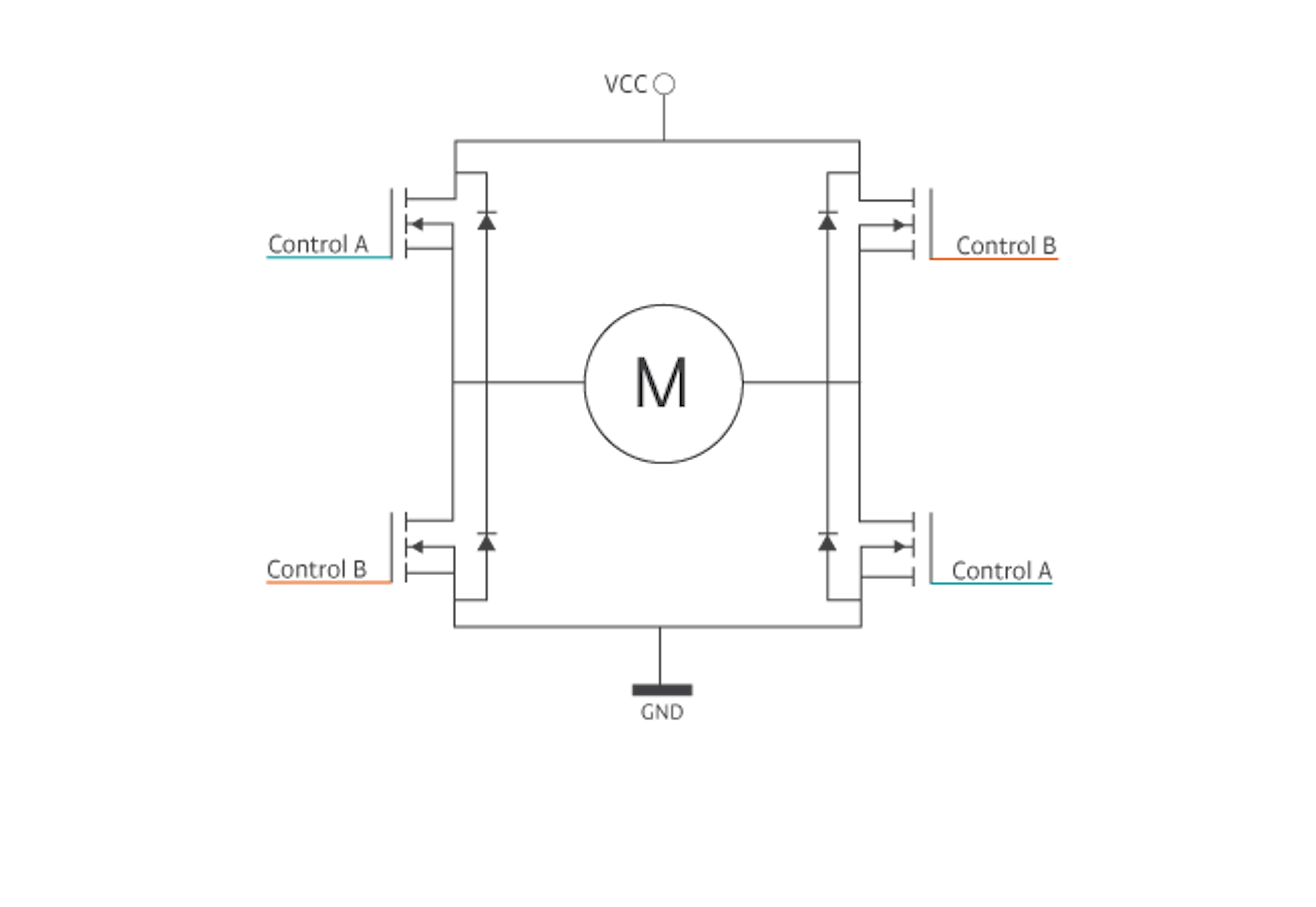
- MOSFET (metal-oxide-semiconductor field-effect transistor). Transistor switches These bridges can control low-to-medium power motors. They are the most common bridges used in robotics. The MOSFET transistors can manage higher power levels than the BJT switches, they are easy-to-use, and they can switch faster than the BJT switches. This allows for better motor control.
The H-Bridge can have other components that are used as switches, like IGBT (Insulated Gate Bipolar Transistor) or other high-power components. These types of H-Bridges are used to control high-power motors in industrial applications.
CONNECTING TO MICROCONTROLLERS
When controlling motors from a microcontroller, is not recommended to connect the output pins of the microcontroller directly to the motor terminals as the motor’s current demand can damage the chip. Usually, the voltage required to power the H-Bridge (and therefore, the motors) is higher than the voltage powering the microcontroller. H-bridges are also used as motor drivers, as they provide the necessary amount of current and voltage to the motor while safely controlling it with 5/3.3V signals from the microcontroller.
The current that a motor consumes is proportional to its torque. Usually, the motors indicate maximum consumption for maximum torque (e.g., 1.5A for 19.61Nm). When choosing an H-Bridge, it is important to select one with a current rate that is higher than your motor consumption. If the motor consumes more current than the H-Bridge can supply, it may lead to overcurrent damage.
CONTROLLING SPEED
We can change the speed of a motor by controlling the current that runs through it. A similar effect can be achieved by changing the status of the switches that make up the H-Bridge. Speed control H-Bridges typically use transistors as switches. It is important to note that the switching speed of the transistors in the H-Bridge matters. The frequency of the PWM can only be as much as is allowed by the transistors’ switching speeds.
Depending on the direction of the motor, only a couple of switches are triggered, while the other two are kept open. At this point, the first few switches will be opened and closed by a certain frequency that determines the speed of the motor.
The faster the switches, the better the control over the motor. In order to control the transistors, we need a control signal called pulse width modulation (PWM). This is further explained in the next section of this chapter.
H-BRIDGES ARCHITECTURES
Two different types of H-Bridges exist, depending on the architecture.
- Half Bridge: This model is used in applications where only speed, not directional motor control, is needed.
The speed of the motor could be controlled using only one transistor, but most half bridges have two. This allows a larger current to travel through the motor, therefore yielding a higher speed.
- Complete Bridge: This bridge model allows full control of the motor movements, as explained above.
One common mistake with the H-Bridges is when the user tries to control a stepper motor. This is not possible, as the internal morphology of the motors is different.
H-BRDIGES IN THE KIT
In this kit, we are going to use two different motor driver ICs (H-Bridges): the DVR8871 and the MC33926. The DRV8871 is a smaller chip, and it will be used for standard performance. The chips are controlled through I2C via the SAMD11 microcontroller present in the Motor Carrier. This driver has a current sense resistor that limits the amount of current the chip can drive. In the motor carrier, the current is limited to 3A.
The MC33926 motor driver can be used when higher performance is required. The driver is connected directly to the MKR microcontroller board and provides current feedback through one of the analog-to-digital converters. In addition, the amount of current the driver can handle increases to 5A (absolute maximum rating). For example, this driver is required to move the inertia wheel of the motorcycle, since a higher amount of current is needed in order to obtain the desired response.
TO LEARN MORE
More information about the drivers can be found below.
3.5 PWM
DESCRIPTION
Pulse Width Modulation, or PWM, is a digital modulation technique commonly used to control the power supplied to electrical devices, like motors. The modulation technique consists of changing the width of a periodic signal’s pulse. The width of the pulse is referred to as the duty-cycle and goes from 0% (minimum width) to 100% (maximum width).
CONTROLLING LEDS AND MOTORS
Some electric devices, like LEDs or motors, can be controlled using an analog signal. The higher the voltage applied, the brighter the LED or the faster the motor spins. However, due to the intrinsic low-pass filter nature of these devices, they can be controlled using a PWM signal.
To visualize how PWM functions, let's look at an LED. When an LED turns on, it doesn’t immediately go from OFF to fully ON. Instead, it starts as OFF and glows brighter. It’s almost instantaneous and not visible to the naked eye. But if you could turn off the LED before it reached 100% brightness, and then keep switching it on and off without ever letting the LED reach its maximum output, then the LED will glow less. Doing this repeatedly and quickly enough will make the LED look like it is only glowing at 25% of its full brightness. This switching is the “pulse” part of the PWM—pulsing on and off. It should be also noted that the human eye is also of a low-pass nature, and that contributes to the enhancement of this effect.
The same premise applies to a DC motor. In order to reduce the speed of the motor, you can lower the duty cycle of the PWM signal that goes to the motor driver. The motor’s inertia (its inability to immediately stop when no more energy is being provided) combined with the properties of coils (that don’t allow for sudden changes of current within the coils), is what contributes to PWM being able to control the speed.
PWM IN MICROCONTROLLERS
Most microcontrollers have the capability to generate dedicated PWM signals. Typically, not all the digital pins have this secondary option, so you must check the datasheet if you need a PWM signal to see which pins have this capability. There are also libraries that you can use to generate “software” PWM signals in any GPIO (General Purpose Input/Output) pin.
In the Arduino boards, PWM pins are denoted with a “tilde” ~ symbol next to the pin number. On an Arduino MKR1000, the pins are 2, 3, 4, and 5.

In this kit we will be using PWM signals to control the speed of all the DC motors in the three projects.
TO LEARN MORE
Read more about PWM and how to generate PWM signals from an Arduino board below.
- Arduino’s reference: analogWrite
- Arduino’s reference: description of PWM
- Arduino’s reference: the secrets of Arduino’s PWM
3.6 Ultrasonic Sensors
DESCRIPTION
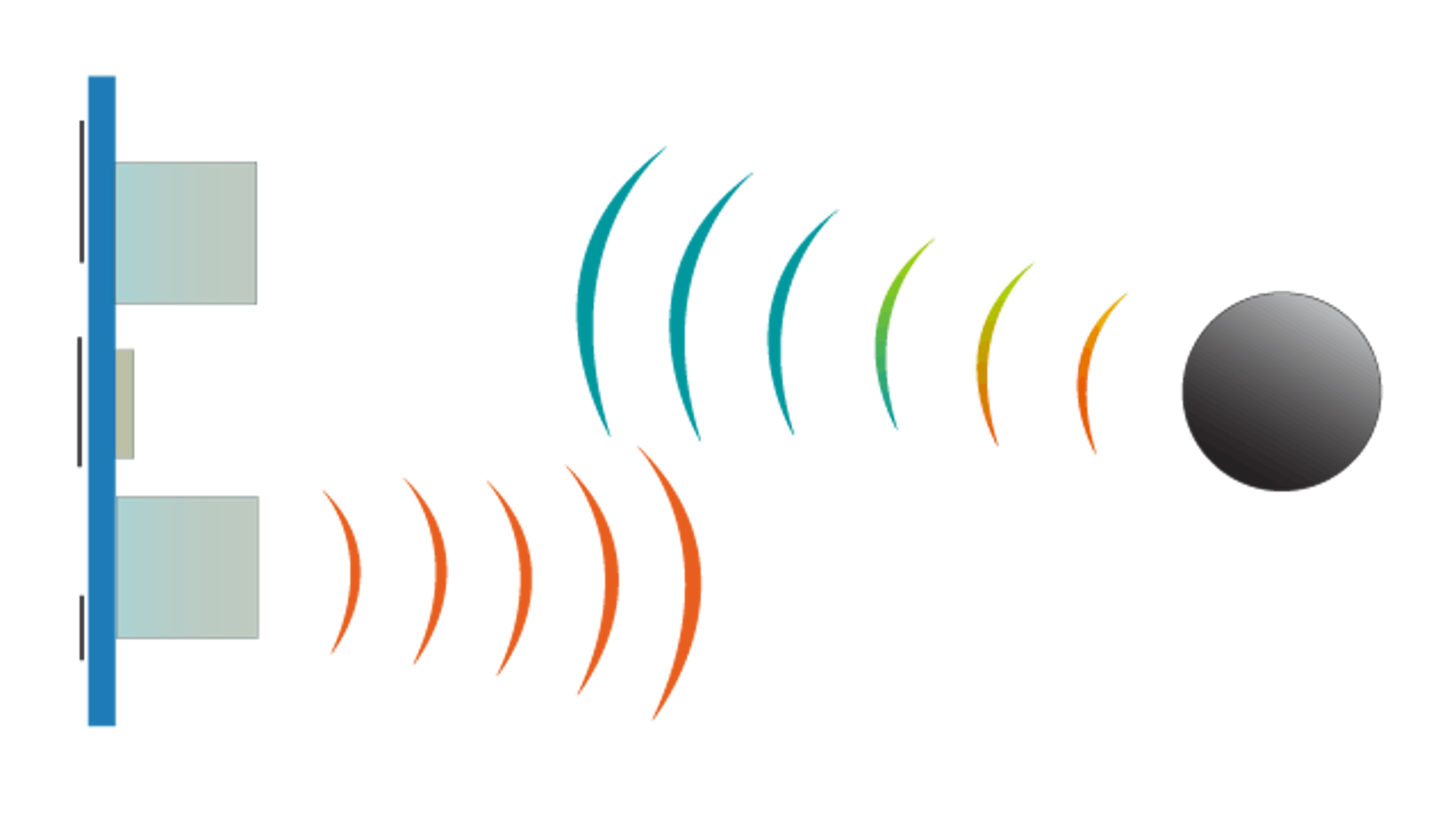
Ultrasonic range sensors detect the distance to the closest object in front of the sensor (sometimes even more than one object). They measure distance by sending out a high frequency sound burst and listening for whatever is bouncing back. Note that this sound is typically out of the auditory range for humans, as well as domestic animals. By measuring the elapsed time between the emitted sound burst and the one received, it is possible to estimate the distance to the object in front of the sensor.
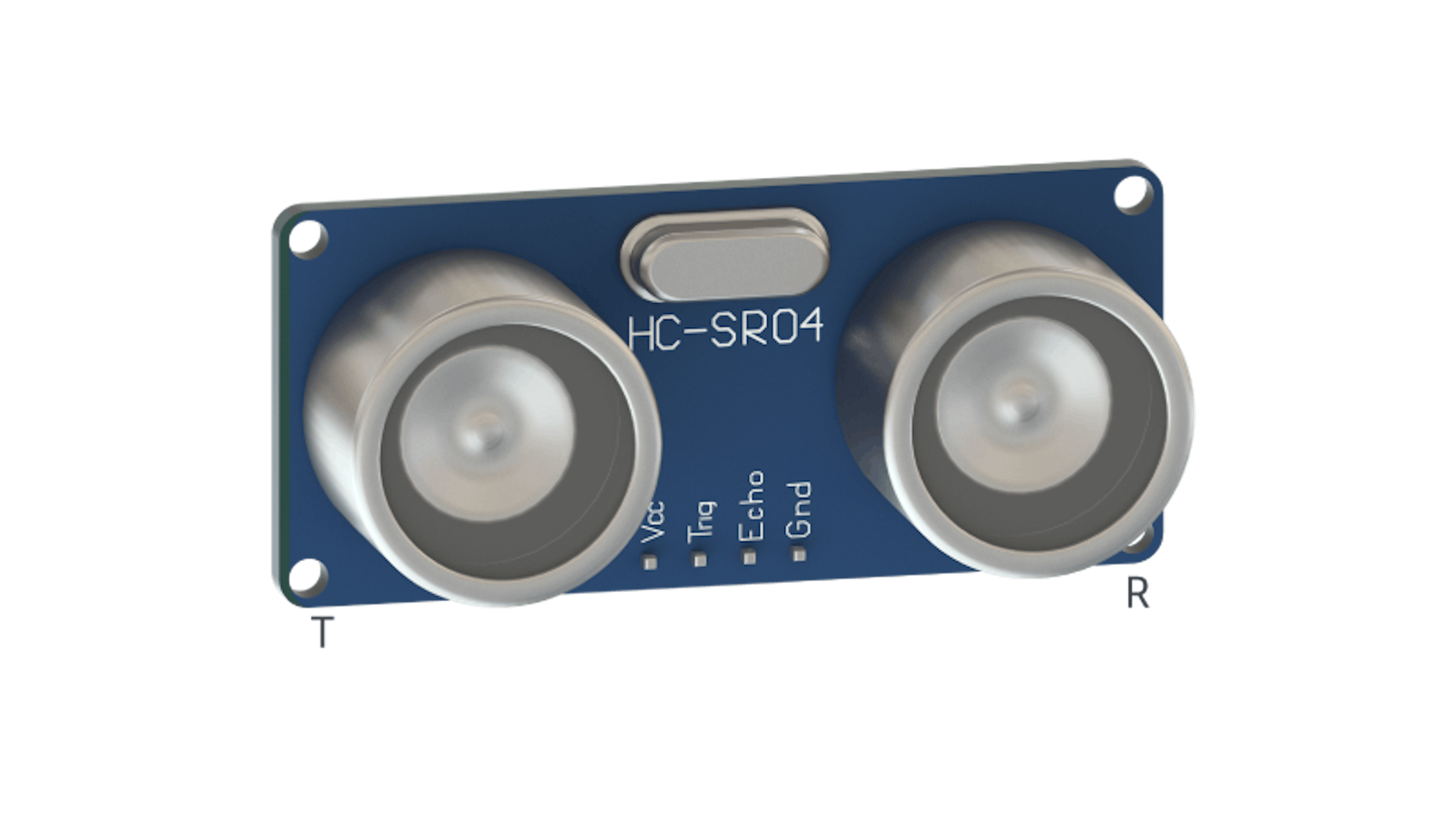
Low-cost ultrasonic sensors generally have two transducers and they look like small cylinders. One transmits the high frequency pulse, and the other receives the returning wave. In the image above, the sensors are marked “T” for transmitter on the left and “R” for receiver on the right. However, there are high-end ultrasonic sensors that use a single transducer that can be switched into an emitting or receiving mode whenever necessary.
THE PROPERTIES OF SOUND WAVES
Under normal environmental conditions, sound travels at around 332 meters per second (1,087 ft/s). If you take the elapsed time between the emitter sending the burst and the receiver getting it back (also known as time of flight), then multiply it by the speed of sound and divide by two (because the signal goes and comes back), it will result in a pretty accurate measurement of the distance to whatever object was in front of the sensor.
$distance=\frac{(time\;of\;flight\times speed\;of\;sound)}2$
Note that the ultrasonic sensor’s accuracy changes with environmental conditions, as the speed of sound changes due to variances in temperature or humidity. Also, if you use several ultrasonic sensors in close proximity to one another, the sound wave from one sensor can be picked up by one of the other ones. This also affects the accuracy.
ULTRASONIC SENSOR IN THE KIT
The sensor has four terminal pins: PWR, GND, Trig (trigger), and Ech (echo). The measurement is performed by having the microcontroller send a pulse a couple of microseconds in duration to the sensor via the Trig pin. From that moment, the sensor activates the Ech pin. This signals that there is a sound burst being emitted, flying towards an object, and bouncing back. The Ech pin is kept on HIGH until the front of the sound burst is echoed back into the receiver transducer. In other words, the microcontroller can obtain the time of flight by measuring the length of time the Ech pin is in the HIGH state.
There are also 3-pin ultrasonic sensors. They function like the 4-pin ones, but the Echo and Trig pins are combined into one Signal pin. This pin will then act as both the trigger of the sound and the receiver when the sound comes back. In that case, the microcontroller board will have to interactively change the mode of the pin from INPUT to OUTPUT during program execution. The Arduino language and hardware allow for this.
In the kit, the ultrasonic sensor will be used in the motorcycle project and the rover project as obstacle avoidance systems. Detecting an object in front of the vehicle will stop the motors or make them change direction.
HARDWARE TEST
To test the ultrasonic ranging module we will use a sketch that reads from this sensor and returns the distance to the closest object in range. To do this, the arduino sends a pulse to the sensor to initiate a reading, then listens for a return pulse. The latency of the returning pulse is proportional to the distance from the object. Connect the parts like shown in the wiring tab in the Create window.
MATERIALS
- MKR Motor carrier
- Module cable
- Ultrasound sensor
- MKR1000
- Battery
- USB cable In order to test this component, follow the wiring shown below and upload the code to your MKR1000:
EXPECTED RESULTS
The sketch shows in the serial monitor the distance read from the sensor in inches, cm and mm.
TROUBLESHOOTING
- Make sure the module is connected to the corresponding input in your code: IN1, IN2, IN3 or IN4.
- Make sure the cable is connected in the right direction to the ultrasonic module, the black cable needs to connect to ground (GND pin) on the sensor. The sensor will break if connected in any other way when powering up the board.
- Make sure that the cable is modified correctly like shown here (one of the cable’s in the cable assembly needs to be moved from the 2nd to the 4th position).
- Set the power switch on the carrier to “on”.
- Make sure that the battery is connected correctly with the black wire connected to ground (GND).
Wire orientation of the module cable plays an important role for ultrasonic sensor to function properly. Observe that on the 4-pin header of the module cable, white wire should be next to the red wire. If it is on the wrong place on your module cable, you can watch the video above for relocating it.
TO LEARN MORE
More information about the HC-SR04 ultrasonic sensor can be found below.
3.7 Hall sensor module
DESCRIPTION
As described in the encoders section, a hall sensor is a transducer that varies its output voltage depending on the magnetic field density surrounding the device. There are many applications for this type of sensors including proximity switching, speed detection and current sensing applications. In this kit we will use a Hall Sensor Module to measure the speed of the inertia wheel in the motorcycle project. We will have two small magnets embedded in the inertial wheel and we will place the module close enough to it so we can detect the magnets passing on every spin.
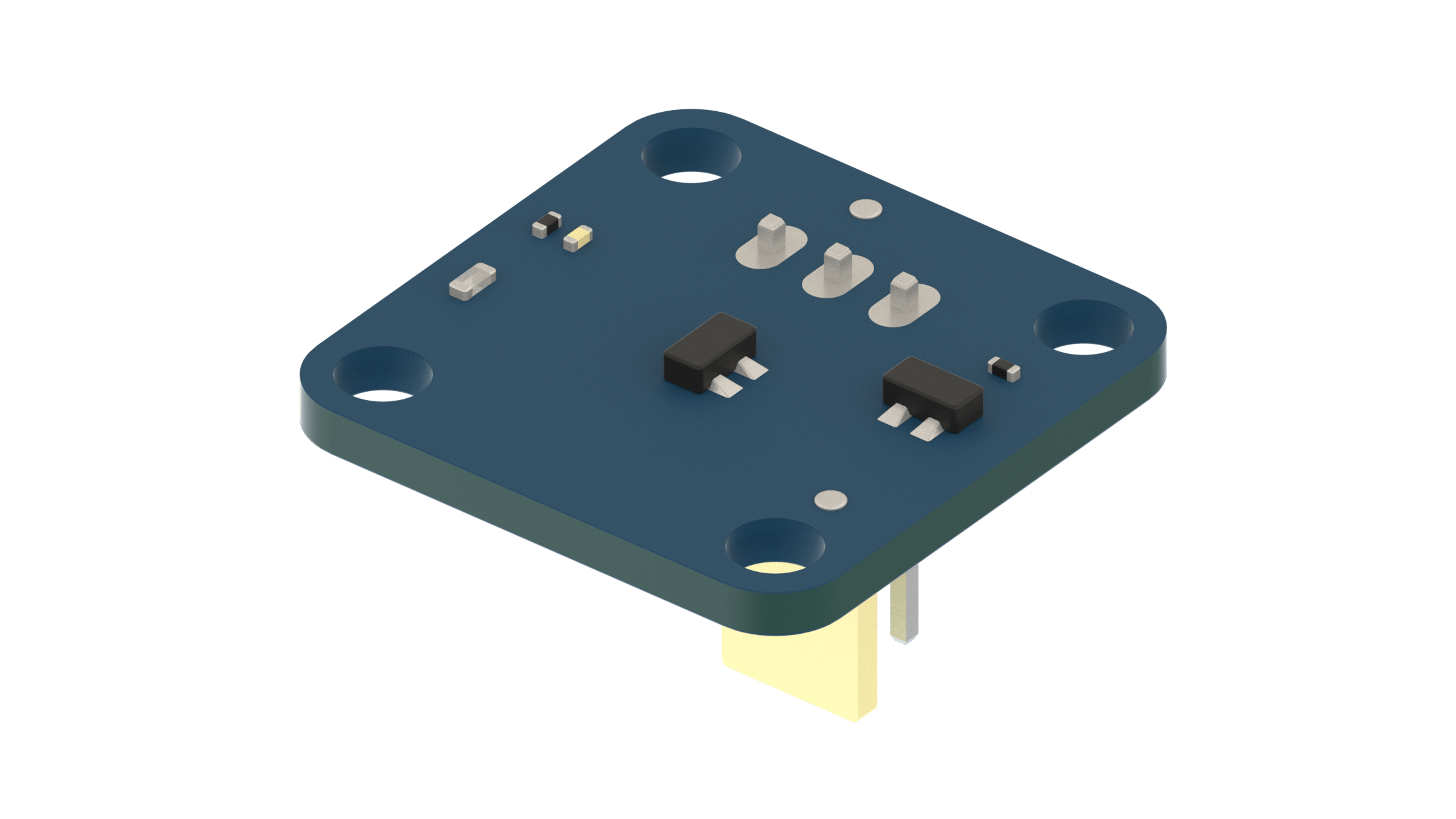
The module included in the kit contains the SL353HT Hall Sensor from Honeywell. This particular device features high switching speed and low current consumption.
HARDWARE TEST
To test the hall sensor module we will use a sketch in the Arduino IDE that increase a counter every time a magnet is approached to the module. You can use the magnet included in the kit that will be used on the inertia wheel in the motorcycle project. After gathering the materials, connect the parts as shown in the wiring tab in the create window.
MATERIALS
- MKR Motor carrier
- 3 wire sensor cable (short)
- Hall sensor module
- MKR1000
- Battery
- USB cable
- Magnet
In order to test this component, follow the wiring shown below and upload the code to your MKR1000:
EXPECTED RESULTS
After loading the code you should be able to see in the console that the counter increases when the magnet is close to the hall sensor module.
TROULESHOOTING
Take a look at the following tips before running the sketch:
- Make sure that the sensor cable is connected correctly to the corresponding input in the code ( IN1, IN2, IN3 or IN4).
- Turn on the power switch on the carrier.
- Make sure that the battery is connected correctly with the black wire connected to ground (GND)
TO LEARN MORE
More information about the HC-SR04 ultrasonic sensor can be found below: SL353HT Datasheet
3.8 Inertial Measurement Unit (IMU)
DESCRIPTION
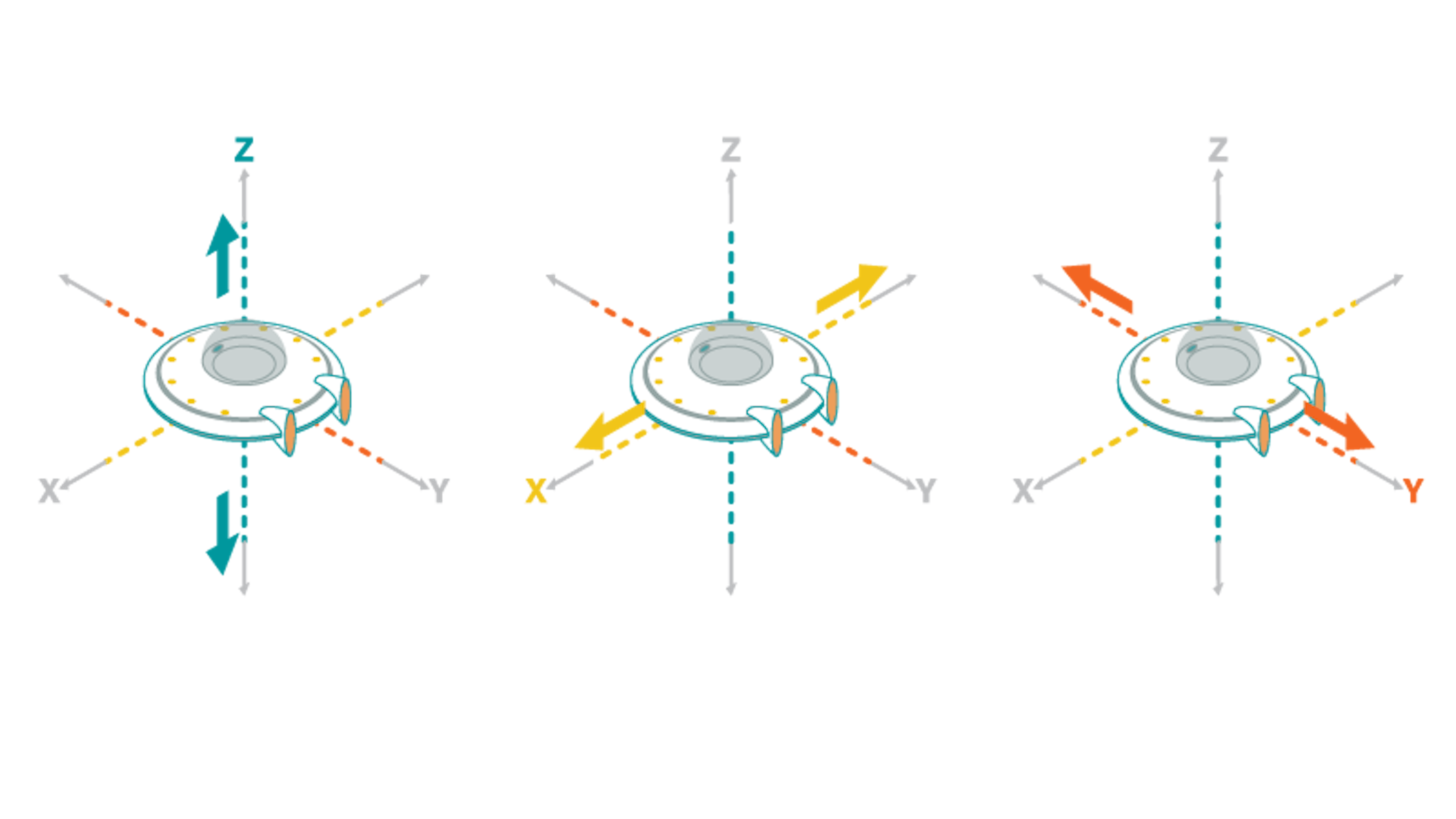
An IMU (Inertial measurement unit) is an electronic module that measures how the module behaves under changes in linear acceleration, angular rotation, and, in some cases, the magnetic field around the module. Thus, IMU modules include different sensors, accelerometers, gyroscopes, and magnetometers, in a single housing.
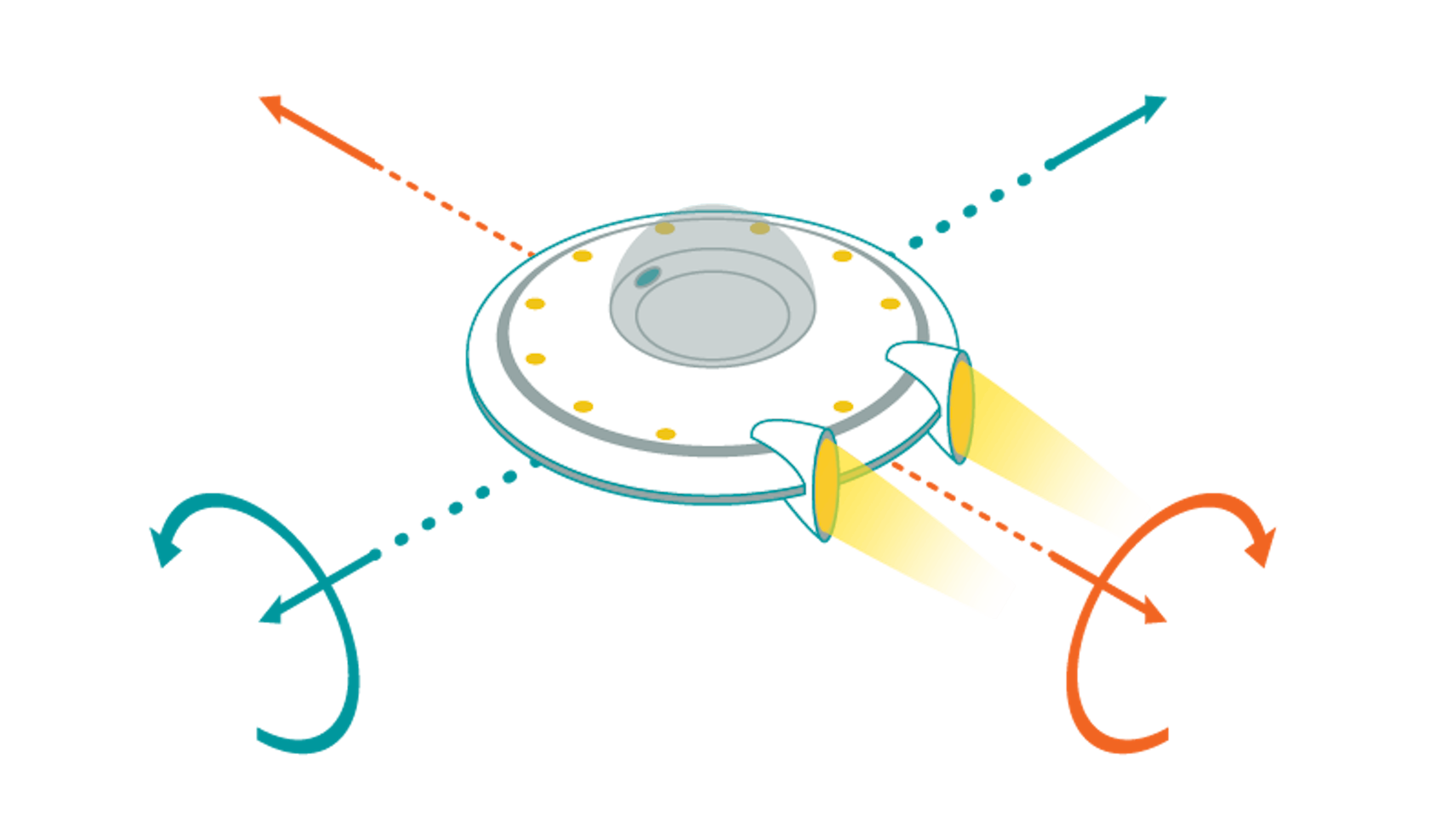
The raw data coming from the sensors on the IMU is then processed and combined into other information that is easier to use in our projects. The information we extract is referred to as: pitch, roll, and yaw. Each one of these measurements correlates to one of the X, Y, or Z axes.
ACCELEROMETER

The accelerometer can measure the speed (linear velocity) and the changes in the object to which it is attached. During stress or through intense vibrations caused by movement, the sensing element generates different amounts of voltage. The movement data is then provided as an x, y, and z value set.
GYROSCOPE
The gyroscope detects orientation. Using gravity as a basis for measurement, it uses x, y, and z values to provide rotation data. Gyroscopes can be used to measure rotation rate (angular velocity).
MAGNETOMETER
The magnetometer measures magnetism. In IMU modules, they are generally used to detect the relative change in a magnetic field at a particular direction. Magnetometers are typically used to provide a heading reference for our electronic device. Despite its usefulness, not all IMU modules have a magnetometer. Using one improves the accuracy of the measurements, and the addition of a magnetometer to the module will give a North Magnetic Pole reference point.
THE IMU IN THE KIT
In this kit, we are going to use an IMU to measure the vertical position of the self-balancing motorbike and detect when it is falling. More concretely, we will use the Arduino IMU Shield, which will sit on top of the MKR1000, to send the information via I2C. This shield features the BN0055, a 9-axis (acc+gyro+magnetometer) orientation sensor.
In order to communicate with the sensor, the MKR1000 makes use of the BNO055 IMU library . You can download the "BNO055" library and install it using the library manager.

HARDWARE TEST
To test the IMU shield for the MKR1000 we will use a sketch that calculates the Yaw, Roll and Pitch values using the Euler data from the IMU shield. The IMU shield communicates with the MKR1000 using the I2C protocol so we need to plug the shield on top of the MKR1000. Make sure the shield is plugged in the right direction! See the illustration for clarification.
MATERIALS
- MKR1000
- IMUShield
- USB cable
In order to test this component, follow the wiring shown in the second tab in the Create Window below and upload the code to your MKR1000.
EXPECTED RESULTS
You should be able to see the 3 values changing when you move the MKR1000 together with the IMU shield. The angle range for each parameter are:
- Pitch: 0 to 360 degrees
- Yaw: -180 to 180 degrees
- Roll: -90 to 90 degrees
TROUBLESHOOTING
- Make sure you plug the board in the right direction (the labeling on the silk and the connector should match)
TO LEARN MORE
More information about the IMU we used can be found here:
- The filtering processes required to make sense of the raw sensor data can be found at: IMU Data Fusing: Complementary, Kalman, and Mahony Filter
- To compare the datasheet to the sensor on the IMU Shield: BNO055 Orientation Sensor Datasheet
3.9 I2C Communication
DESCRIPTION
I2C (Inter-Integrated-Circuit) is a bus-based serial communication protocol that allows a device (master) to establish a communication with different peripherals (slaves) using only two signal pins: SDA (data signal) and SCL (clock signal). Both master and slave devices require some sort of microcontroller to be on board to handle the I2C communication protocol. Each slave has to be connected to both signals, and each needs a unique address identifier. Typically, addresses are set up at the time of manufacturing, and many devices do not allow for address changes. The master can communicate individually with slaves using their unique addresses.
The schematic of a I2C protocol hardware connection is shown below.
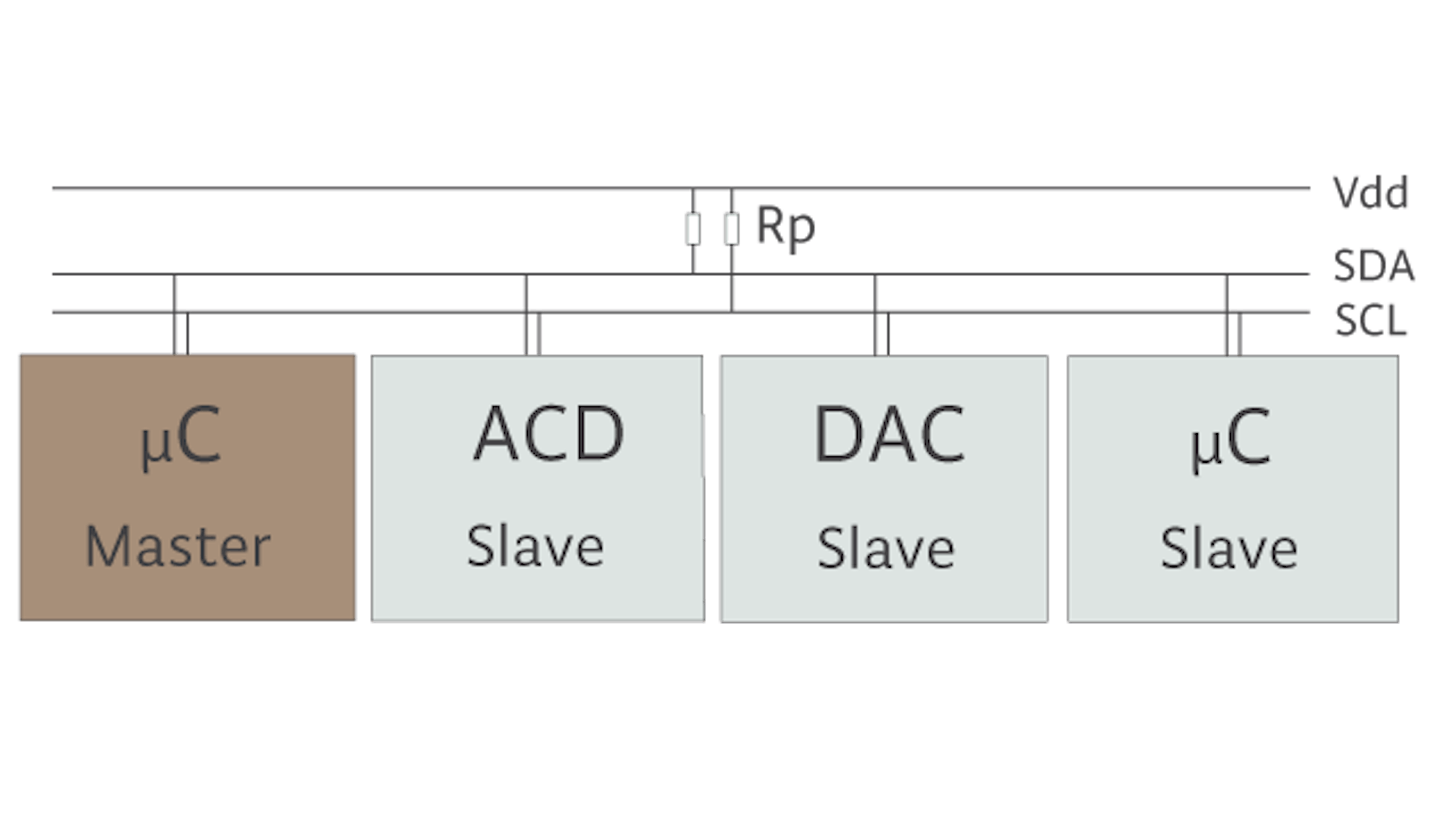
SDA and SCL bus wires require a pull-up resistor, which typically is 10 KOhm. Many microcontrollers that are used as masters in I2C implementations come with their own internal pull-up resistors.
THE PROTOCOL
I2C is a synchronous communication protocol. The SCL signal is responsible for providing synchronism between the master and the slaves for every data transfer. The SDA signal pin handles bidirectional data transfers. In other words, the pins from the microcontrollers on the master and slave devices have to switch from INPUT to OUTPUT during run time.
The step-by-step communication protocol is described in the following sequence.
- Start Condition
- Slave address + Write/Read flag
- Acknowledge
- Data transference
- Acknowledge
- Stop Condition
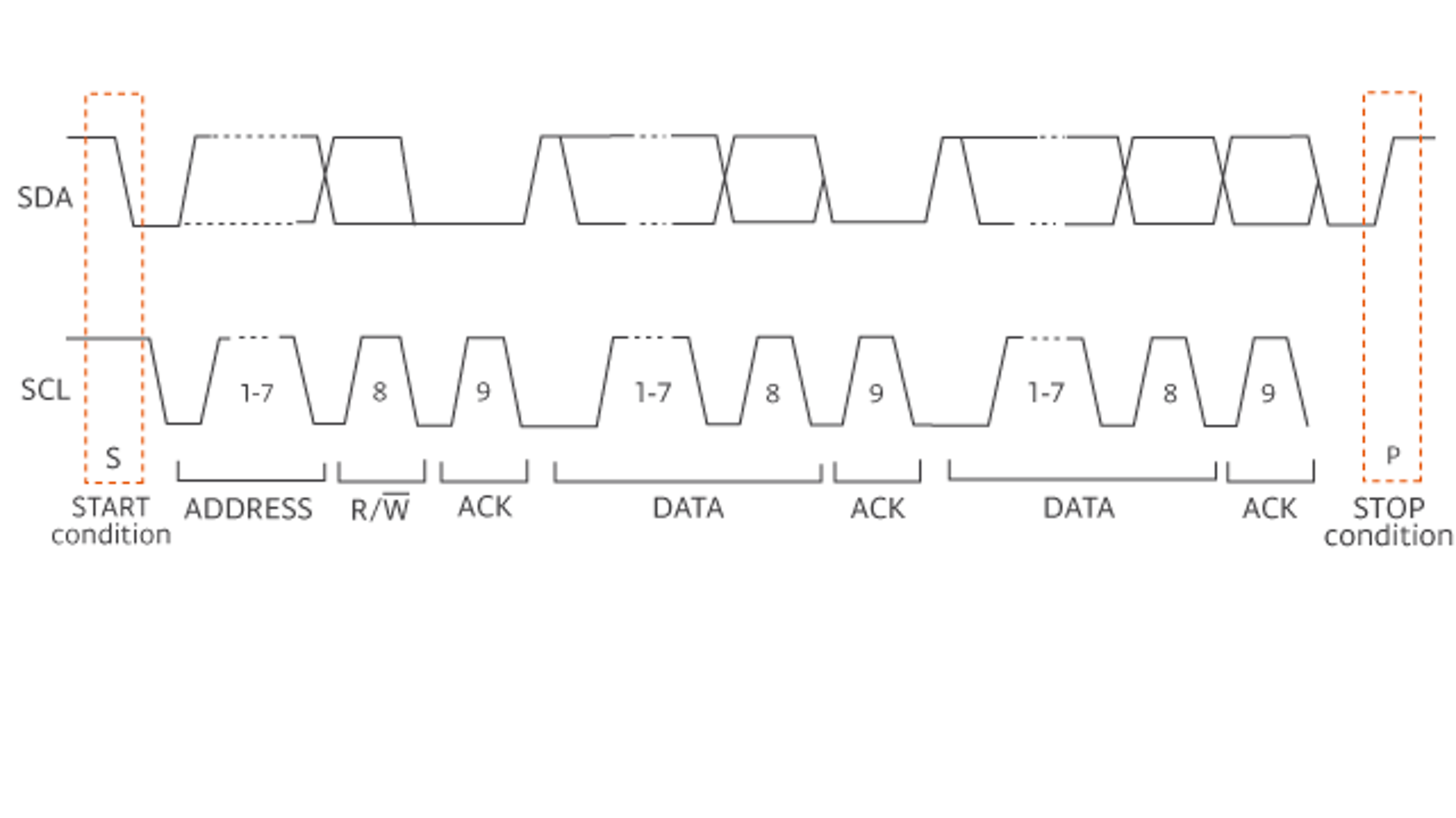
Every data transfer is initialized and finalized by a "start" or "stop" condition. This condition constitutes a specific position for the SDA and SCL lines for a certain amount of time.
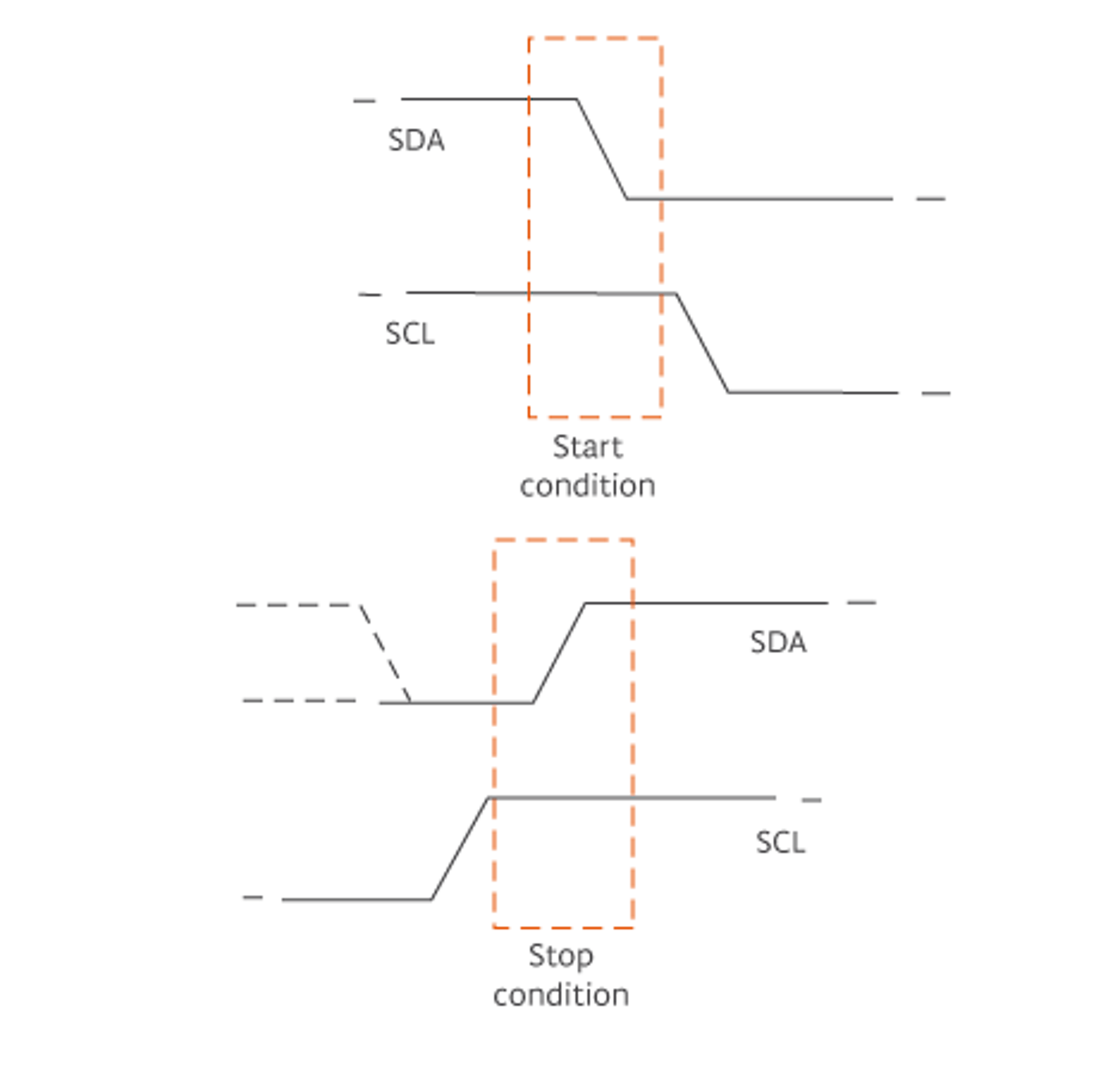
The first image shows the SDA and SCL signal statuses for a START transference condition. The second picture shows the SDA and SCL signal statuses for a STOP transference condition.
Once the start condition occurs, the SCL starts a clock signal that will last until the end of the data transfer. At the same time, the master has to send a frame through the SDA signal with the address of the slave it wants to communicate with.
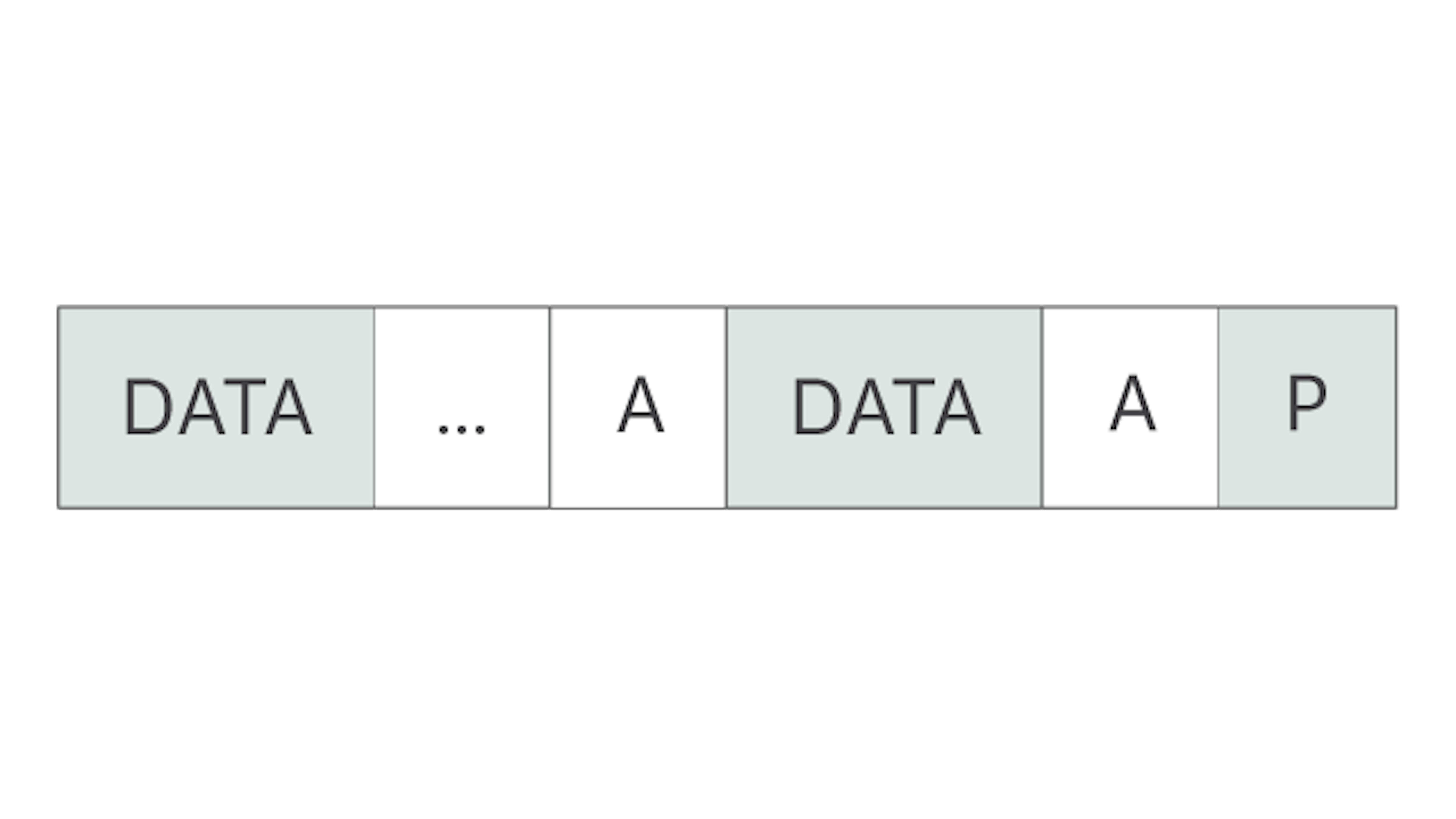
Each frame that will be sent is 8 bits long and follows the below structure.
- The slave address takes 7 bits. This implies there can be up to 127 different devices on the bus.
- The 8th bit is to tell the slave if the next step is to send data to the master (read function) or to receive data from the master (write function).
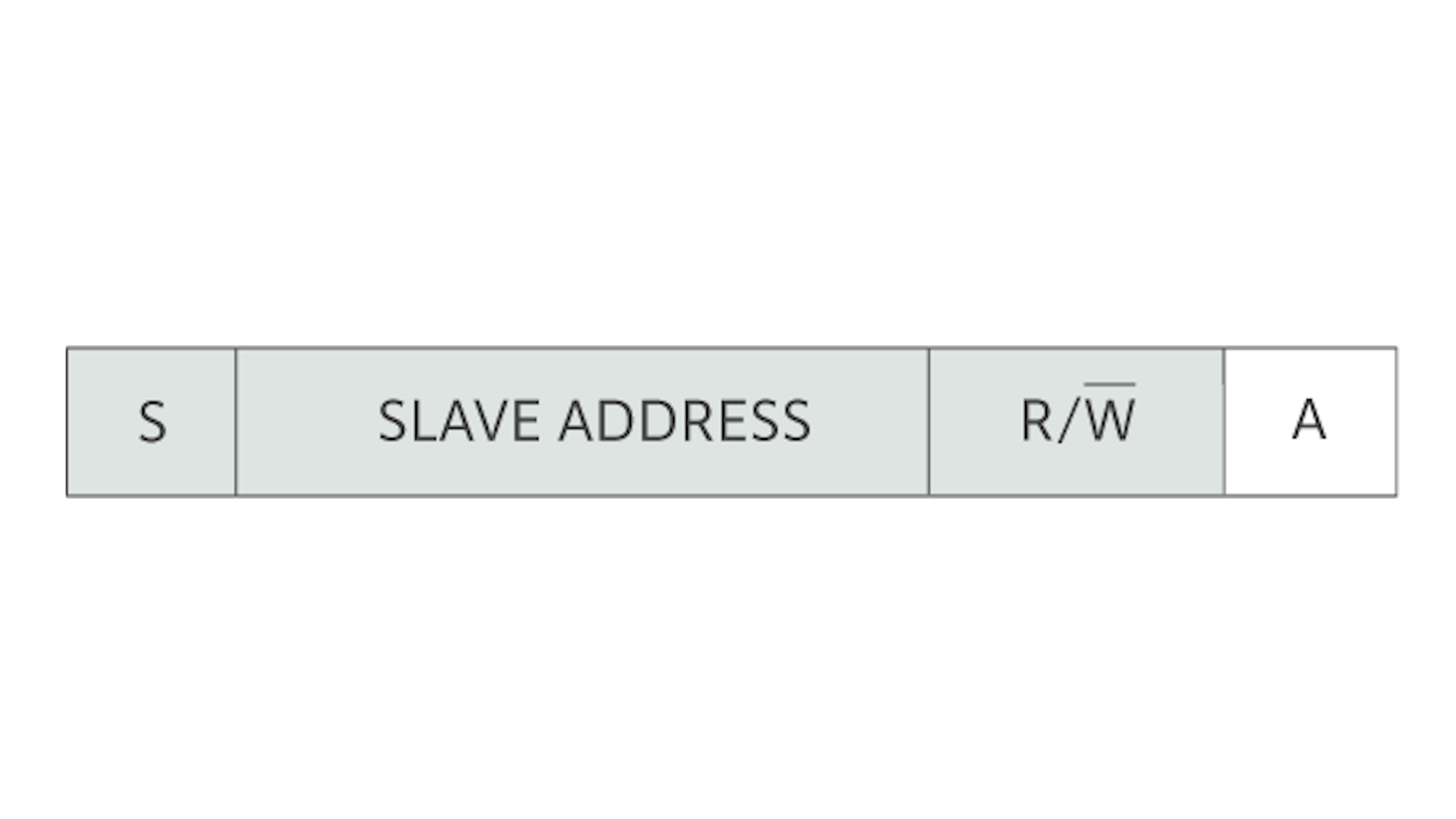
The image above shows the structure of the first half of the communication between the master and a slave.
- Start condition (S)
- Slave address with the Read/Write bit
- Acknowledge (A)
The acknowledgement is sent by the slave that received the frame, and it indicates that the data has been received and processed. This means that the device is ready for the next step. Once the first frame has been sent and processed by the slave, and the acknowledgement has arrived at the master, the actual data transfer starts. This last data transfer is through frames that are 8 bits long, followed by an acknowledgement from the device that receives the data from the device that sends it. The structure of this communication is below.
The last step in the communication is the stop condition, which occurs when all the data has been sent. Once the stop condition occurs, the communication is finished. If the master needs more information from the peripheral, it has to start a new communication process following all of the above steps.
Below is the sequence of a complete data transference between master and slave.
LIMITATIONS OF I2C
How many peripherals can be connected to the I2C bus?
Even if the address space for I2C is 127 (as described earlier), there is another limitation that might not allow I2C chains to become too long. The specifications of I2C allow 400pF as the maximum capacitive load in the bus. Every peripheral has a capacitance (indicated in the component datasheet) that is added to the total load (since all slaves are connected in parallel). Therefore, depending on the components used, the number of peripherals that can connect at once will change.
Data Transference Speed
There are different implementation options for this protocol, and each one allows for a different data transfer speed.
I2C IN THE KIT
In the projects within this program, the MKR1000 will use I2C communication to get data from the IMU shield and to send commands to the SAMD11 microcontroller located in the motor carrier.
TO LEARN MORE
More information about the I2C protocol can be found below.
3.10 Interrupts
DESCRIPTION
In order to understand how interrupts work, we first need a brief explanation of how the microcontrollers execute programs.
When we write a program, we write a series of instructions that tell the CPU and peripherals in the microcontroller what they have to do. Once the program is uploaded to the microcontroller, every instruction is executed sequentially. This means that the execution of the next instruction will not start until the one prior is finalized.
An interrupt is a signal in a microcontroller that informs the CPU about an event that needs immediate attention. When an interrupt occurs, the controller puts its main execution sequence on hold and jumps to run another portion of code that is called the Interrupt-Service-Routine (ISR) or interrupt handler. An interrupt handler is only executed when an interrupt happens. Once the interrupt handler has ended, the main program execution resumes in exactly the place where it was interrupted.
We can use interrupts to know the exact moment when something is happening. For example, we can use interrupts to know when one encoder makes a tick.
TYPES OF INTERRUPTS
Interrupts are associated with status changes. We have different types of interrupts, internal and external, depending on the source of the interrupt signal.
- The internal interrupts are triggered when the change is produced in one of the microcontroller internal registers. It could be a failure inside the microcontroller, a timer, a change in a specific register, and so forth.
- The external interrupts are triggered when the status change is produced in a peripheral. Interrupts can be triggered from the change on a specific pin. We can program the system’s behavior when this kind of interrupt happens by programming an interrupt handler function.
MASKABLE VERSUS NON-MASKABLE
We can also classify the interrupts as maskable and non-maskable:
-
Maskable interrupts: these interrupts can be masked. This means that when it is triggered, the microcontroller does not attend the handler routine for the interrupt.
-
Non-maskable interrupts: every time that these interrupts are triggered, the handler routine is executed. These interrupts have the highest priority level. Inside this group is the RESET signal to the CPU.
INTERRUPT PRIORITY
Inside of each type of interrupt, there is a priority system that handles the order in case two or more are triggered at the same time. When this happens, the highest priority interrupt is executed first, and the others enter into a pending status until the system is available for execution.
There are three different statuses for an interrupt.
- Inactive: The interrupt condition does not happen.
- Pending: The interrupt condition has happened, but the handler routine is not yet executed.
- Run: The handler routine is executed.
Every status is controlled with a flag in an internal register of the microcontroller. This allows users to know and modify the status of the interrupt handler.
THE INTERRUPT HANDLER
The interrupt handler is a function that executes a specific task. We have to program it accordingly to what we need when the interrupt condition happens.
When we program an interrupt handler, we have to follow the below guidelines.
- There has to be enough time between two interrupt conditions to execute the interrupt handler function. Therefore, the interrupt handler execution has to be short enough to allow the main program to execute between two interrupt conditions.
- Loops should not be used in the interrupt handler program, as they sometimes don't allow a return to the main program execution.
- Before leaving the interrupt handler function, we have to reset the “status flag”. In some microcontrollers, this is done automatically, but we have to modify some registers manually in others.
INTERRUPTS IN THE KIT
In this kit, we are using interrupts to count the number of encoder ticks. This operation is done inside the SAMD11 controller within the motor carrier in order to offload some processing power from the main controller in the MKR1000.
3.11 LiPo batteries
DESCRIPTION
Lithium polymer (LiPo) batteries are a newer type of batteries that are popular for applications where weight and shape are critical, like in tablets and phones. These batteries are based on lithium-ion technology, which uses a semisolid polymer electrolyte instead of a liquid one. This allows LiPo batteries to be made in any size or shape and to be much lighter than other lithium batteries. However, the sensitive chemistry inside the LiPo batteries makes them more fragile and can lead to fire if the battery gets punctured.
We define batteries with a rating system. There are three main ratings on a LiPo battery: voltage, capacity, and discharge.
VOLTAGE
Voltage (3.7 V in this case) is the first rating. Batteries are quantified in cells, or standard units of power storage. Each LiPo cell has a nominal voltage of 3.7 V. In many batteries, multiple cells are added in series. This means that the voltage gets added together. Therefore, batteries with 2 cells are 7.4 V, batteries with 3 cells are 11.1 V, and so forth.
As a matter of note, the nominal voltage is the default, resting voltage of a battery pack. This is how the battery industry standardizes and compares batteries. However, this does not represent the full charge voltage of the cell. LiPo batteries are fully charged when they reach 4.2v/cell, and their minimum safe charge is 3.0v/cell. 3.7v is a median value, and that is the nominal charge of the cell.
CAPACITY (1000 mAh)
The capacity of a battery is the measurement of how much power the battery can hold, much like the size of the fuel tank in a car. The unit of measure for the capacity is in milliamp hours (mAh), which represents how much current must be extracted from the battery to discharge it in one hour.
Consequently, the capacity determines how long a battery can run before it needs to be recharged. As the capacity increases in newer batteries, so it does the length of the run time. However, the size, weight, and recharge time also increases.
DISCHARGE RATING
The discharge rating (65C in this case), C, is a measure of how fast the battery can be safely discharged without harming it. It is not a standalone number, as it has to be considered along with the capacity to give relevant information.
$capacity\;\times\;discharge\;rating\;=\;safe\;amp\;draw$
Hence, for the example above:
:1800 x 65 = 117000 mA
BATTERY LIFE AND POTENTIAL RISKS
As its name indicates, lithium polymer batteries contain lithium. Lithium is an alkali metal, which means that it reacts with water and combusts. Lithium also combusts when it reacts with oxygen, but only when heat is applied. The process of using the battery causes excess oxygen and lithium atoms to accumulate on either end (cathode or anode) of the battery. This can cause lithium oxide (Li2O) to build up on the anode or cathode. The Li2O causes the internal resistance of the battery to increase. The result of higher internal resistance is that the battery will heat up more during use.
As a note, internal resistance is best described as the measure of opposition a circuit presents to the passage of current.
The lithium oxide build-up usually takes around 300-400 charge/discharge cycles before a tipping point is reached. Therefore, that is the typical life of a LiPo battery. However, if we heat the batteries up during a run, discharge them at less than 3.0 volts per cell, physically damage them in any way, or allow water to enter the batteries, the battery life is reduced. This hastens the buildup of Li2O.
Lipos must be handled with care. Discharging the battery under the minimum safe charge can cause irreparable damage to the battery. Therefore make sure to keep track of the battery voltage level in your projects (e.g. adding safety measures in your code or circuit) to avoid harming your battery. In addition, overcharging it can cause the battery to ignite. For this reason, Lipo batteries should always be charged with a specialized charger, and you may never leave your Lipos unattended during charging.
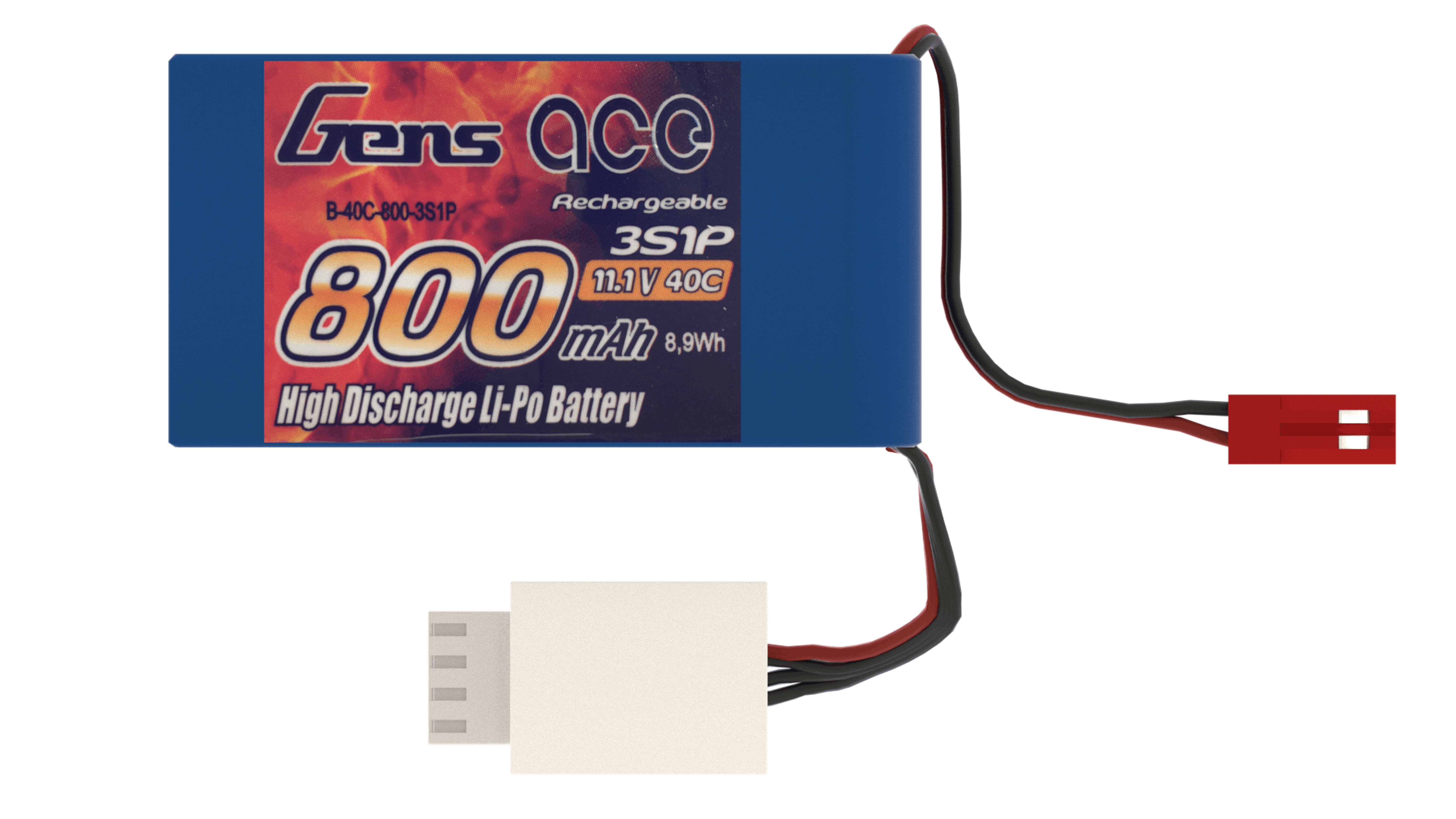
LIPO BATTERY IN THE KIT

The above picture depicts the battery that is used for this project.
- 800 mAh is the capacity. It represents how much can be put on the battery to discharge it in one hour.
- 11.1 V is the voltage. This means that the battery is composed of three LiPo cells.
- 40C is the discharge rating, which represents how fast the battery can be discharged without harming it. This value, multiplied by the capacity, provides a safe Amp draw.
800 x 40=32000 mA

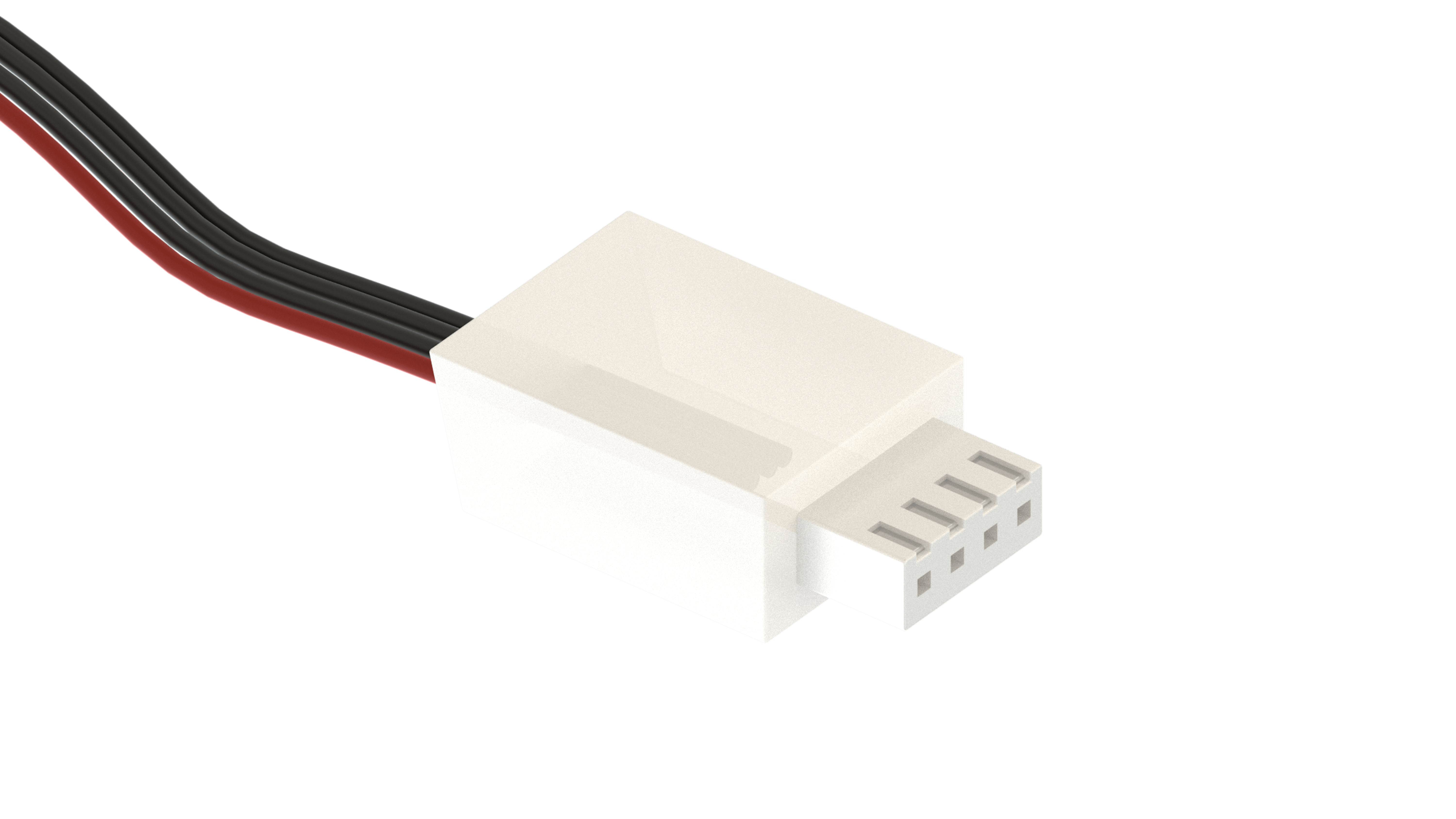
In most cases, LiPo batteries come with two connectors; one to discharge the battery (top connector in the image) and one to recharge it (bottom). It is important not to confuse them, as this can harm the battery.
The connector used to recharge the battery has three different ground wires, one for each cell, so as to charge them individually. Charging the battery with the wrong connector can cause the cell to overcharge.